
Datasheet

PCA9551_8 © NXP B.V. 2008. All rights reserved.
Product data sheet Rev. 08 — 31 July 2008 2 of 26
NXP Semiconductors
PCA9551
8-bit I
2
C-bus LED driver with programmable blink rates
n No glitch on power-up
n Supports hot insertion
n Low standby current
n Operating power supply voltage range of 2.3 V to 5.5 V
n 0 Hz to 400 kHz clock frequency
n ESD protection exceeds 2000 V HBM per JESD22-A114, 150 V MM per
JESD22-A115 and 1000 V CDM per JESD22-C101
n Latch-up testing is done to JEDEC Standard JESD78 which exceeds 100 mA
n Packages offered: SO16, TSSOP16, HVQFN16
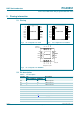
3. Ordering information
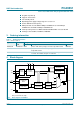
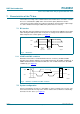
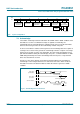
4. Block diagram
Table 1. Ordering information
T
amb
=
−
40
°
C to +85
°
C.
Type number Topside
mark
Package
Name Description Version
PCA9551D PCA9551D SO16 plastic small outline package; 16 leads; body width 3.9 mm SOT109-1
PCA9551PW PCA9551 TSSOP16 plastic thin shrink small outline package; 16 leads;
body width 4.4 mm
SOT403-1
PCA9551BS 9551 HVQFN16 plastic thermal enhanced very thin quad flat package;
no leads; 16 terminals; body 4 × 4 × 0.85 mm
SOT629-1
Only one I/O shown for clarity.
Fig 1. Block diagram of PCA9551
A0 A1 A2
002aac504
I
2
C-BUS
CONTROL
INPUT
FILTERS
PCA9551
POWER-ON
RESET
SCL
SDA
V
DD
V
SS
LEDn
RESET
OSCILLATOR
PRESCALER 1
REGISTER
PRESCALER 0
REGISTER
PWM1
REGISTER
PWM0
REGISTER
INPUT
REGISTER
LED SELECT (LSn)
REGISTER
BLINK0
BLINK1
0
1