
Datasheet

PCF2123 All information provided in this document is subject to legal disclaimers. © NXP B.V. 2013. All rights reserved.
Product data sheet Rev. 6 — 15 July 2013 33 of 64
NXP Semiconductors
PCF2123
SPI Real time clock/calendar
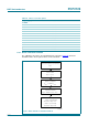
8.11 STOP bit function
The function of the STOP bit is to allow for accurate starting of the time circuits. The STOP
bit function will cause the upper part of the prescaler (F
2
to F
14
) to be held in reset and
thus no 1 Hz ticks will be generated. The time circuits can then be set and will not
increment until the STOP bit is released (see Figure 22
and Table 41).
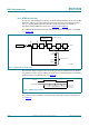
The STOP bit function will not affect the output of 32.768 kHz, 16.384 kHz, or 8.192 kHz
(see Section 8.8
).
The lower two stages of the prescaler (F
0
and F
1
) are not reset and because the SPI-bus
is asynchronous to the crystal oscillator, the accuracy of re-starting the time circuits will be
between 0 and one 8.192 kHz cycle (see Figure 22
).
The first increment of the time circuits is between 0.499878 s and 0.500000 s after STOP
bit is released. The uncertainty is caused by the prescaler bits F
0
and F
1
not being reset
(see Table 41
).
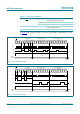
Fig 21. STOP bit functional diagram
001aai556
OSCILLATOR
32768 Hz
16384 Hz
OSCILLATOR STOP
DETECTOR
F
0
F
1
F
13
RESET
F
14
RESET
F
2
RESET
2 Hz
1 Hz
1024 Hz
16384 Hz
8192 Hz
1 Hz tick
stop
CLKOUT source
oscillator stop flag
8192 Hz
4096 Hz
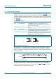
Fig 22. STOP bit release timing
001aaf912
8192 Hz
stop released
0 μs to 122 μs