
Datasheet

Philips Semiconductors
PCF8594C-2
512 × 8-bit CMOS EEPROM with I
2
C-bus interface
Product data Rev. 05 — 25 October 2004 13 of 21
9397 750 14221
© Koninklijke Philips Electronics N.V. 2004. All rights reserved.
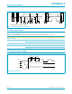
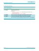
Fig 11. n bytes E/W cycle (n = 2 to 7).
t
d
t
HIGH
f
t
r
t
LOW
t
STOP
12PTC
SDA
SCL
MBA698
n x 256 + 1
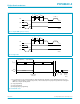
Fig 12. Page mode.
t
d
t
HIGH
f
t
r
t
LOW
t
STOP
12PTC
SDA
SCL
MBA699
1153
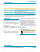
(1) If an external clock is chosen, this information is latched internally by setting pin 7 (PTC) LOW after transmission of the
eighth bits of the word address (negative edge of SCL). Thus the state of pin 7 may be previously undefined. Leaving pin 7
LOW causes a higher standby current.
(2) 1-byte programming.
(3) 2-byte programming.
(4) One page (8 bytes) programming.
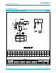
Fig 13. External clock.
S
0 A A DATA A DATA A
P
SLAVE ADDRESS WORD ADDRESS
(1)
undefined
1
1
1
2
2
2
257
513
1153
clock (2)
clock (3)
clock (4)
d
t 0
negative edge
SCL 8-bit
undefined
LOW
HIGH
PTC
2
I C-bus
MBA700