
Reference guide

Software Description
Software Implementation
Cluster for Motorbikes Using the MC68HC908LJ12 and MC33970 DRM059
MOTOROLA Software Description 53
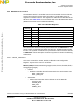
4.3.3 MC33970 Device Control
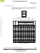
The MC33970 device is controlled from the microcontroller via the 16-bit SPI
protocol and reports back the status information. The MC33970 uses six
registers to control the device. The registers are addressed via D15:D13 of the
SPI word. See
Table 4-10. For more details refer to the MC33970 Data Sheet
(Motorola document order number MC33970/D).
The control of the device is done by macros defined in the GDIC970.h file. The
macro creates a 16-bit SPI data word and calls SPI_SendRecv16(tU16 data)
function. The symbolic constants for the parameters of the macros are defined
in GDIC970.h. A short description of all macro syntaxes is made in the following
subsections.
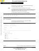
4.3.3.1 PECCR_CMD Macro
This macro controls the “Power, Enable, Calibration and Configuration
Register”. Syntax of the macro is as follows:
PECCR_CMD(nullcmd,statusselect,gaugepos,rtzloc,aircore,clkcalsel,clkcal,o
scadj,gauge1,gauge0)
• nullcmd
– Enables or disables the Null Command for the device Status read.
NULL_CMD_ENA
NULL_CMD_DIS
• statusselect
– Selects the information that is clocked out of the MISO bit
STATUS_OUT
ACCUM_OUT
POS_OUT
SPEED_OUT
Table 4-10. MC33970 Registers
Address
[D15:D13]
Name Use
000 PECCR Power, Enable, Calibration and Configuration Register
001 VELR Maximum Velocity Register
010 POS0R Gauge 0 Position Register
011 POS1R Gauge 1 Position Register
100 RTZR Return to Zero Register
101 RTZCR Return to Zero Configuration Register
110 N.A. Not Used
111 N.A. Reserved for Test
Frees
cale Semiconductor,
I
Freescale Semiconductor, Inc.
For More Information On This Product,
Go to: www.freescale.com
nc...