MF0ICU2 MIFARE Ultralight C - Contactless ticket IC Rev. 3.3 — 30 July 2019 137633 1 Product data sheet COMPANY PUBLIC General description NXP Semiconductors has developed the MIFARE Ultralight C - Contactless ticket IC MF0ICU2 to be used in a contactless smart ticket or smart card in combination with Proximity Coupling Devices (PCD). The communication layer (MIFARE RF Interface) complies to parts 2 and 3 of the ISO/IEC 14443 Type A standard (see Ref. 1 and Ref. 2).
MF0ICU2 NXP Semiconductors MIFARE Ultralight C - Contactless ticket IC 1.3 Security • • • • • 3DES Authentication Anti-cloning support by unique 7-byte serial number for each device 32-bit user programmable OTP area Field programmable read-only locking function per page for first 512-bit Read-only locking per block for the memory above 512 bit 1.4 Naming conventions Table 1.
MF0ICU2 NXP Semiconductors MIFARE Ultralight C - Contactless ticket IC • 36 pages, 1152-bit user r/w area • Field programmable read-only locking function per block • Field programmable read-only locking function per page for first 512-bit • 16-bit one-way counter • 32-bit user definable One-Time Programmable (OTP) area • Write endurance 100000 cycles • Data retention of 10 years 3 Quick reference data Table 2.
MF0ICU2 NXP Semiconductors MIFARE Ultralight C - Contactless ticket IC Type number Package Name MF0MOU2101DA8 PLLMC 5 Description Version MOA8 plastic leadless module carrier package; 35 mm wide tape; 50 pF input capacitance SOT500-4 Block diagram DIGITAL CONTROL UNIT CRYPTO CO PROCESSOR antenna RF-INTERFACE CRYPTO CONTROL UNIT EEPROM EEPROM INTERFACE COMMAND INTERPRETER 001aah999 Figure 2. Block diagram 6 Pinning information 6.
MF0ICU2 NXP Semiconductors MIFARE Ultralight C - Contactless ticket IC 7 Functional description 7.1 Block description The MF0ICU2 chip consists of a 1536-bit EEPROM, an RF-Interface and the Digital Control Unit. Energy and data are transferred via an antenna, which consists of a coil with a few turns directly connected to the MF0ICU2. No further external components are necessary. For details on antenna design please refer to the document Ref. 7.
MF0ICU2 NXP Semiconductors MIFARE Ultralight C - Contactless ticket IC POR IDLE HALT REQA WUPA WUPA READY 1 ANTICOLLISION SELECT of cascade level 1 READ from address 0 HALT HALT READY 2 READ from address 0 identification and selection procedure ANTICOLLISION SELECT of cascade level 2 WRITE of 4 byte ACTIVE READ of 16 byte memory operations AUTHENTICATE WRITE of 4 byte AUTHENTICATED READ of 16 byte 001aai000 Remark: In each state the command interpreter returns to the Idle state if an u
MF0ICU2 NXP Semiconductors MIFARE Ultralight C - Contactless ticket IC • With the cascade level 1 SELECT command the PCD transits the MF0ICU2 into the READY2 state where the second part of the UID can be resolved • With the READ (from page address 00h) command the complete anticollision mechanism may be skipped and the MF0ICU2 changes directly into the ACTIVE state Remark: If more than one MF0ICU2 is in the field of the PCD, a read from address 0 will cause a collision because of the different serial numb
MF0ICU2 NXP Semiconductors MIFARE Ultralight C - Contactless ticket IC state via the HLTA command. This state helps the PCD to distinguish between already processed cards and cards that have not been selected yet. The only way to get the MF0ICU2 out of this state is the WUPA command or a RF reset. Any other data received in this state is interpreted as an error and the MF0ICU2 remains in this state. 7.2.
MF0ICU2 NXP Semiconductors MIFARE Ultralight C - Contactless ticket IC Page address Byte number Decimal Hex 0 1 2 3 41 29h 16-bit counter 16-bit counter - - 42 2Ah authentication configuration 43 2Bh authentication configuration 44 to 47 2Ch to 2Fh authentication key 7.5.1 UID/serial number The unique 7 byte serial number (UID) and its two Block Check Character Bytes (BCC) are programmed into the first 9 bytes of the memory.
MF0ICU2 NXP Semiconductors MIFARE Ultralight C - Contactless ticket IC MSB L 7 L 6 L 5 L 4 L OTP BL 15-10 BL 9-4 LSB MSB BL OTP L 15 LSB L 14 L 13 L 12 L 11 L 10 L 9 L 8 page 2 0 1 2 3 lock byte 0 Lx locks page x to read-only lock byte 1 BLx blocks further locking for the memory area x aaa-006277 Figure 6. Lock bytes 0 and 1 For example if BL15-10 is set to logic 1, then bits L15 to L10 (lock byte 1, bit[7:2]) can no longer be changed.
MF0ICU2 NXP Semiconductors MIFARE Ultralight C - Contactless ticket IC Any write operation to the lock bytes 0 and 1, features anti-tearing support. Remark: The configuration written in the lock bytes is valid upon the next REQA or WUPA command. 7.5.3 Lock byte 2 and 3 To lock the pages of the MF0UL21 starting at page address 10h onwards, the lock bytes 2 and 3 located in page 28h (byte 0 and 1 as shown in Figure 7) are used.
MF0ICU2 NXP Semiconductors MIFARE Ultralight C - Contactless ticket IC Any write operation to the lock bytes 2 and 3, features anti-tearing support. Remark: The configuration written in the lock bytes is valid upon the next REQA or WUPA command. 7.5.4 OTP bytes Page 3 is the OTP page. It is preset to all "0" after production. These bytes may be bitwise modified by the WRITE or COMPATIBILITY WRITE command.
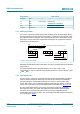
MF0ICU2 NXP Semiconductors MIFARE Ultralight C - Contactless ticket IC # PCD Data exchanged PICC 2 3 ← "AFh" || 8 bytes ek(RndB) The PCD itself generates a 8 byte random number RndA. This RndA is concatenated with RndB’ and enciphered with the key. Rn dB’ is generated by rotating the original Rnd B left by 8 bits. This token ek(RndA || RndB’) is sent to the PICC. 4 5 The PICC generates a 8 byte random number RndB.
MF0ICU2 NXP Semiconductors MIFARE Ultralight C - Contactless ticket IC # PCD Data exchanged PICC 2 ← generate RndB = 51E764602678DF2B AF577293FD2F34CA51 IV = 0000000000000000 ek(RndB) = 577293FD2F34CA51 3 decipher ek(RndB) to retrieve RndB generate RndA = A8AF3B256C75ED40 RndB’ = E764602678DF2B51 RndA+RndB’ = A8AF3B256C75ED40E764602678DF2B51 IV = 577293FD2F34CA51 ek(RndA+RndB´) = 0A638559FC7737F9F15D7862EBBE967A → AF0A638559FC7737F9 F15D7862EBBE967A 4 ← decipher ek(RndA+RndB´) to retrieve RndA 003
MF0ICU2 NXP Semiconductors MIFARE Ultralight C - Contactless ticket IC Table 11. Memory content based on example configuration Byte address 0h 1h 2h 3h Page address Byte 0 Byte 1 Byte 2 Byte 3 2Ch Page 44 07 06 05 04 2Dh Page 45 03 02 01 00 2Eh Page 46 0F 0E 0D 0C 2Fh Page 47 0B 0A 09 08 The memory pages holding the authentication key can never be read, independent of the configuration.
MF0ICU2 NXP Semiconductors MIFARE Ultralight C - Contactless ticket IC Table 13. Initial memory organization Page address Byte number dec. hex.
MF0ICU2 NXP Semiconductors MIFARE Ultralight C - Contactless ticket IC write data page 29h content counter bytes Byte Nr initial WRITE F0 00 00 00 increment by 1 01 00 00 00 increment by 15 0F 00 00 00 increment by 15 0F 00 00 00 increment by 7 07 00 00 00 0 1 2 3 00 00 00 00 F0 00 00 00 F1 00 00 00 00 01 00 00 0F 01 00 00 16 01 00 00 aaa-013579 Figure 9.
MF0ICU2 NXP Semiconductors MIFARE Ultralight C - Contactless ticket IC 8.2 Timings The timing shown in this document are not to scale and values are rounded to 1 μs. All given command and response transmission times refer to the data frames including start of communication and end of communication. A PCD data frame contains the start of communication (1 "start bit") and the end of communication (one logic 0 + 1 bit length of unmodulated carrier).
MF0ICU2 NXP Semiconductors MIFARE Ultralight C - Contactless ticket IC Answer value Answer explanation 2h NAK for EEPROM write error 1h NAK for parity or CRC error 0h NAK for any other error After every NAK, the MF0ICU2 performs an internal reset and returns to IDLE or HALT state. Remark: Any 4-bit response different from Ah shall be interpreted as NAK, although not all 4-bit values are detailed in Table 15 8.
MF0ICU2 NXP Semiconductors MIFARE Ultralight C - Contactless ticket IC A roll-over mechanism is implemented to continue reading from page 00h once the end of the accessible memory is reached. For example, reading from address 29h on a MF0ICU2 results in pages 29h, 2Ah, 2Bh and 00h being returned.
MF0ICU2 NXP Semiconductors MIFARE Ultralight C - Contactless ticket IC Table 20 shows the required timing. PCD Cmd Addr Data CRC ACK PICC ,,ACK'' TACK 708 µs 57 µs PICC ,,NAK'' NAK TNAK 57 µs TTimeOut Time out aaa-006286 Figure 12. WRITE Table 19. WRITE command Name Code Description Length Cmd A2h write one page 1 byte Addr - page address ‘02h’ to ‘2Fh’ 1 byte CRC - CRC according to Ref. 2 2 bytes Data - data 4 bytes NAK see Table 15 see Section 8.3 4-bit Table 20.
MF0ICU2 NXP Semiconductors MIFARE Ultralight C - Contactless ticket IC PCD Cmd Addr CRC ACK PICC ,,ACK'' TACK 368 µs 59 µs NAK PICC ,,NAK'' TNAK 59 µs TTimeOut Time out 001aan015 Figure 13. COMPATIBILITY WRITE part 1 PCD Data CRC ACK PICC ,,ACK'' TACK 1558 µs 59 µs NAK PICC ,,NAK'' TNAK 59 µs TTimeOut Time out 001aan016 Figure 14. COMPATIBILITY WRITE part 2 Table 21.
MF0ICU2 NXP Semiconductors MIFARE Ultralight C - Contactless ticket IC 9.5 AUTHENTICATE Description: The authentication process is detailed Section 7.5.5. The command is performed in the same protocol as READ, WRITE and COMPATIBILITY WRITE. Executing a HALT command results in losing the authentication status. PCD Cmd Arg CRC 8 Byte ek(RndB) PICC ,,ACK'' D7 D6 ... D1 D0 AFh TACK 368 µs CRC 953 µs PICC ,,NAK'' NAK 57 µs TNAK TTimeOut Time out aaa-013577 Figure 15.
MF0ICU2 NXP Semiconductors MIFARE Ultralight C - Contactless ticket IC 16 Byte ek(RndA || RndB') PCD Cmd D7 ... D0 D7 ... D0 CRC 8 Byte ek(RndA') PICC ,,ACK'' 00h D7 D6 ... D1 D0 TACK 1642 µs CRC 953 µs PICC ,,NAK'' NAK TNAK 57 µs TTimeOut Time out aaa-013578 Figure 16. AUTHENTICATE Step 2 Table 26.
MF0ICU2 NXP Semiconductors MIFARE Ultralight C - Contactless ticket IC Symbol Parameter Tamb ambient temperature VESD [1] [1] electrostatic discharge voltage on LA/LB Min Max Unit -25 +70 °C 2 - kV ANSI/ESDA/JEDEC JS-001; Human body model: C = 100 pF, R = 1.5 kΩ CAUTION This device has limited built-in ElectroStatic Discharge (ESD) protection.
MF0ICU2 NXP Semiconductors MIFARE Ultralight C - Contactless ticket IC treatment ground and stress relieve roughness Ra max = 0.2 μm Rt max = 2 μm Chip dimensions [1] x = 710 μm step size y = 710 μm [1] typical = 22 μm gap between chips minimum = 5 μm Passivation type sandwich structure material PSG / nitride thickness 500 nm / 600 nm Au bump (substrate connected to VSS) material > 99.9 % pure Au hardness 35 to 80 HV 0.
MF0ICU2 NXP Semiconductors MIFARE Ultralight C - Contactless ticket IC PLLMC: plastic leadless module carrier package; 35 mm wide tape SOT500-2 X D A detail X 0 10 scale DIMENSIONS (mm are the original dimensions) UNIT A (1) max. D mm 0.33 35.05 34.95 20 mm For unspecified dimensions see PLLMC-drawing given in the subpackage code. Note 1. Total package thickness, exclusive punching burr.
MF0ICU2 NXP Semiconductors MIFARE Ultralight C - Contactless ticket IC PLLMC: plastic leadless module carrier package; 35 mm wide tape SOT500-4 X D A 0 10 mm detail X scale Dimensions Unit 20 mm A(1) D max 0.26 35.05 nom 35.00 min 34.95 For unspecified dimensions see PLLMC-drawing given in the subpackage code. Note 1. Total package thickness, exclusive punching burr.
MF0ICU2 NXP Semiconductors MIFARE Ultralight C - Contactless ticket IC 12.3 Bare die outline For more details on the wafer delivery forms see Ref. 13. Chip Step Bump size LA, LB, VSS, VDD, TEST x [µm] y [µm] 710(1) 710(1) 60 60 typ. 22(1) min. 5 typ. 22(1) min. 5 MF0ICU2 LA VDD typ. 710(1) 626 528.6 43.5 223.6 TEST GND LB 49.1 y 626 typ.
MF0ICU2 NXP Semiconductors MIFARE Ultralight C - Contactless ticket IC Acronym Description ATQA Answer To ReQuest, type A BCC Block Check Characters byte CBC Cipher-Block Chaining CRC Cyclic Redundancy Check CT Cascade Tag, Type A EEPROM Electrically Erasable Programmable Read-Only Memory fc carrier frequency 13.
MF0ICU2 NXP Semiconductors MIFARE Ultralight C - Contactless ticket IC Application note, BU S&C Doc. No.: 1308** [5] MIFARE Ultralight Features and Hints Application note, BU S&C Doc. No.: 0731** [6] MIFARE Ultralight as Type 2 Tag Application note, BU S&C Doc. No.: 1303** [7] MIFARE (Card) Coil Design Guide Application note, BU S&C Doc. No.: 0117** [8] MF0ICU1 Functional specification MIFARE Ultralight Product data sheet, BU S&C Doc. No.
MF0ICU2 NXP Semiconductors MIFARE Ultralight C - Contactless ticket IC 15 Revision history Table 32. Revision history Document ID Release date Data sheet status Change notice Supersedes MF0ICU2 v. 3.3 20190730 Product data sheet - MF0ICU2 v. 3.2 Modifications: • Updated descriptive text of the default user memory content, Section 7.5.9 • Update of Table 13 MF0ICU2 v. 3.
MF0ICU2 NXP Semiconductors MIFARE Ultralight C - Contactless ticket IC 16 Legal information 16.1 Data sheet status Document status [1][2] Product status [3] Definition Objective [short] data sheet Development This document contains data from the objective specification for product development. Preliminary [short] data sheet Qualification This document contains data from the preliminary specification. Product [short] data sheet Production This document contains the product specification.
MF0ICU2 NXP Semiconductors MIFARE Ultralight C - Contactless ticket IC No offer to sell or license — Nothing in this document may be interpreted or construed as an offer to sell products that is open for acceptance or the grant, conveyance or implication of any license under any copyrights, patents or other industrial or intellectual property rights.
MF0ICU2 NXP Semiconductors MIFARE Ultralight C - Contactless ticket IC Tables Tab. 1. Tab. 2. Tab. 3. Tab. 4. Tab. 5. Tab. 6. Tab. 7. Tab. 8. Tab. 9. Tab. 10. Tab. 11. Tab. 12. Tab. 13. Tab. 14. Tab. 15. Tab. 16. Naming conventions ..........................................2 Characteristics ...................................................3 Ordering information ..........................................3 Pin allocation table ............................................4 Memory organization ...........
MF0ICU2 NXP Semiconductors MIFARE Ultralight C - Contactless ticket IC Contents 1 1.1 1.2 1.3 1.4 2 2.1 2.2 3 4 5 6 6.1 7 7.1 7.2 7.2.1 7.2.2 7.2.3 7.2.4 7.2.5 7.2.6 7.3 7.4 7.5 7.5.1 7.5.2 7.5.3 7.5.4 7.5.5 7.5.6 7.5.7 7.5.8 General description ............................................ 1 Contactless energy and data transfer ................1 Anticollision ........................................................ 1 Security ..............................................................