
Datasheet


NXP Semiconductors
MF0ICU2
MIFARE Ultralight C - Contactless ticket IC
MF0ICU2 All information provided in this document is subject to legal disclaimers. © NXP B.V. 2019. All rights reserved.
Product data sheet Rev. 3.3 — 30 July 2019
COMPANY PUBLIC 137633 15 / 36
Table 11. Memory content based on example configuration
Byte address 0h 1h 2h 3h
Page address Byte 0 Byte 1 Byte 2 Byte 3
2Ch Page 44 07 06 05 04
2Dh Page 45 03 02 01 00
2Eh Page 46 0F 0E 0D 0C
2Fh Page 47 0B 0A 09 08
The memory pages holding the authentication key can never be read, independent of the
configuration.
Remark: A re-programmed authentication key is only valid for authentication after a RF
reset or a re-activation.
7.5.8 Configuration for memory access via 3DES Authentication
The behavior of the memory access rights depending on the authentication is configured
with two configuration bytes, AUTH0 and AUTH1, located in pages 2Ah and 2Bh. Both
configuration bytes are located in Byte 0 of the respective pages (see also Table 5).
• AUTH0 defines the page address from which the authentication is required. Valid
address values for byte AUTH0 are from 03h to 30h.
• Setting AUTH0 to 30h effectively disables memory protection.
• AUTH1 determines if write access is restricted or both read and write access are
restricted, see Table 12
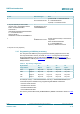
Table 12. AUTH1 bit description
Bit Value Description
1 to 7 any ignored
1 write access restricted, read access allowed without authentication0
0 read and write access restricted
7.5.9 Data pages
The MF0ICU2 features 144 bytes of data memory. The EEPROM memory is organized in
pages with 4 bytes per page. The user memory area ranges from page 04h to 27h.
Remark: The default content of the user memory pages 04h to 27h at delivery is not
defined.
A write access to data memory is done with a WRITE (see Section 9.3) or a
COMPATIBILITY WRITE (see Section 9.4) command. In both cases, 4 bytes of memory
- (one page) - will be written. Write access to data memory can be permanently restricted
via lock bytes (see Section 7.5.2 and Section 7.5.3) and/or permanently or temporary
restricted using an authentication (see Section 7.5.5).
Reading data is done using the READ command (see Section 9.2).
7.5.10 Initial memory configuration
The memory configuration of MF0ICU2 in delivery state is shown in Table 13: