MPC8568E Development Kit Kit Configuration Guide Revised: 21 Feb 2008
Freescale™, the Freescale logo, and CodeWarrior are trademarks or registered trademarks of Freescale Semiconductor, Inc. in the U.S. and/or other countries. The Power Architecture™ and Power.org word marks are trademarks and service marks licensed by Power.org. All other product or service names are the property of their respective owners. Copyright © 1999-2008 by Freescale Semiconductor, Inc. All rights reserved." Copyright © 2008 by Freescale Semiconductor, Inc. All rights reserved.
Table of Contents 1 Introduction 5 Development Kit Components . . . . . . . . . . . . . . . . . . . . . . . . . . . . . . . . . . . . . . . 5 MPC8568E-MDS-PB Board . . . . . . . . . . . . . . . . . . . . . . . . . . . . . . . . . . . . . . 6 CodeWarrior™ Development Studio for Power Architecture™ Processors, Professional/Linux® Application Edition . . . . . . . . . . . . . . . . . . . . . . . . .
Table of Contents 5 Using the CodeWarrior™ QUICC Engine™ Utility 43 Installing the QUICC Engine™ Utility. . . . . . . . . . . . . . . . . . . . . . . . . . . . . . . .43 System Requirements . . . . . . . . . . . . . . . . . . . . . . . . . . . . . . . . . . . . . . . . . .43 Installation Procedure . . . . . . . . . . . . . . . . . . . . . . . . . . . . . . . . . . . . . . . . . .44 Using the QUICC Engine™ Utility . . . . . . . . . . . . . . . . . . . . . . . . . . . . . . . . . .
1 Introduction This document explains how to use each component of the MPC8568E-MDS-PB modular development kit. Specifically, the document explains how to: • Set up the MPC8568E-MDS-PB processor board and connect it to your development PC. • Install CodeWarrior™ Development Studio for Power Architecture™ Processors, Professional Edition. • Install CodeWarrior Development Studio for Power Architecture Processors, Linux® Platform Edition.
Introduction Development Kit Components • The CodeWarrior QUICC Engine Utility (QEU), a GUI-based tool that generates C source code that initializes the QUICC Engine block of the MPC8568E processor. • The CodeWarrior USB TAP debug probe, which lets you control the MPC8568E processor at the hardware level, as well as manipulate flash memory.
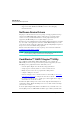
Introduction Development Kit Components CodeWarrior™ Development Studio for Power Architecture™ Processors, Professional/Linux® Application Edition CodeWarrior Development Studio for Power Architecture Processors, Professional Edition combines the CodeWarrior Integrated Development Environment (IDE) with the latest CodeWarrior compiler, linker, and debugger technology. This CodeWarrior tool chain lets you generate programs in executable and linkable (.elf) format. Because .
Introduction Development Kit Components • Display of stack crawl, memory, registers, register details, and cache windows • Support for both the STABS and DWARF (versions 1 and 2) debugging information formats NetComm Device Drivers The purpose of the NetComm Device Drivers package is to help programmers develop software for the MPC8568E family of Power Architecture processors.
Introduction Development Kit Components binary file generated by this project to an MPC8568E-MDS-PB board, the selected QUICC Engine device blocks are configured according to the choices made in the QEU. NOTE This kit supports both Linux and bare board development; however, the QUICC Engine Utility currently supports bare board development only. USB TAP Debug Probe The CodeWarrior USB TAP debug probe lets you control the MPC8568E processor’s execution at the hardware level.
Introduction How this Manual is Organized How this Manual is Organized Table 1.1 provides a brief description of each chapter in this document. Table 1.
Introduction How this Manual is Organized Depending upon the type of development you plan to do, you should read different sections of this document.
Introduction Table of Acronyms Table of Acronyms Table 1.2 lists and defines acronyms used in this manual. Table 1.2 Acronyms Used in this Manual Acronym Description ADS Application Development System A Freescale board that is a platform for developing custom embedded software for a particular Freescale microcontroller. COP Common On-chip Processor Name of connector to which you attach JTAG-type test equipment. DWARF Debug With Arbitrary Record Format.
Introduction Table of Acronyms Table 1.2 Acronyms Used in this Manual (continued) Acronym MDS Description Modular Development System A Freescale system of boards that provides a platform for developing custom embedded software for a particular Freescale microcontroller. An MDS system is more configurable and extensible than is an ADS board. STABS Symbol Table Directives Debugging information format for ELF and other UNIX object file formats. Supports fewer debugger features than DWARF.
Introduction Table of Acronyms 14 MPC8568E Kit Configuration Guide
2 Preparing the MPC8568E-MDS-PB Board This chapter explains how to prepare the MPC8568E-MDS-PB processor board for each type of development you can perform with the MPC8568E kit. NOTE See the MPC8568E-MDS Hardware Getting Started Guide for instructions that explain how to assemble the board. See the MPC8568E-MDS User’s Guide for detailed information about the board’s operation.
Preparing the MPC8568E-MDS-PB Board Preparing for Bare Board Development or for Linux® OS Customization 2. Make power connections. a. Connect the supplied 5 Volt power supply to board power connector P8. b. Connect the supplied power cable between the power supply and a surge-protected power strip. c. Make sure the power strip is turned OFF. d. Connect the power strip to line power. e. Turn on the power supply. 3. Perform initial board power up. a. Press the board power switch (SW5).
Preparing the MPC8568E-MDS-PB Board Preparing for Linux® Application Development Preparing for Linux® Application Development To prepare the MPC8568E-MDS-PB processor board so you can download Linux applications to the board and then debug them using the CodeWarrior debugger, follow these steps: 1. Ensure that power to the board is off. Because the power switch, SW5, is a toggle, verify that the power is off by looking at the board to see that no LEDs are on. 2. Make board-to-computer serial connection. a.
Preparing the MPC8568E-MDS-PB Board Preparing for Linux® Application Development 7. Press the power toggle switch (SW5) to turn on power to the board. The processor board powers up. LD2 and LD7 display a constant green light. LD1 flashes orange once at the end of the reset sequence. The emulator displays Linux boot status messages and then displays this shell prompt: freescale login: (See Figure 2.1.) Figure 2.1 Terminal Emulator Showing Linux® Shell Prompt 8.
Preparing the MPC8568E-MDS-PB Board Preparing for Linux® Application Development 11. Test the processor board’s IP network connection. a. At any computer on the network, enter this command: ping IPAddress (where IPAddress is the IP address you assigned to Ethernet port J10 of the processor board). The ping utility displays messages like these: PING 10.82.191.3 (10.82.191.3): 56 data bytes 64 bytes from 10.82.191.3: icmp_seq=0 ttl=64 time=0.1 64 bytes from 10.82.191.3: icmp_seq=1 ttl=64 time=0.
Preparing the MPC8568E-MDS-PB Board Preparing for Linux® Application Development 20 MPC8568E Kit Configuration Guide
3 Installing CodeWarrior™ Development Studio This chapter explains how to install the CodeWarrior Development Studio product required to perform the type of development you plan to perform. Next, the chapter explains how to register this product.
Installing CodeWarrior™ Development Studio Installing the Bare Board Development Tools Table 3.1 Professional Edition — System Requirements (continued) Operating system • Microsoft® Windows 2000, Windows XP Free disk space • May require as much as 2 GB, depending on the choices selected. Additional space required for project files Installation Procedure NOTE If you are using a USB TAP debug probe, disconnect it from your PC before beginning the CodeWarrior software installation.
Installing CodeWarrior™ Development Studio Installing the Bare Board Development Tools NOTE If you are installing CodeWarrior for Power Architecture Processors, v8.7 rather than v8.8, the wizard welcome page will have v8.7 rather than v8.8 in it. Figure 3.2 CodeWarrior™ Install Wizard — Welcome Page 3. Follow the wizard’s on-screen instructions to install the CodeWarrior software and the desired GCC toolchains.
Installing CodeWarrior™ Development Studio Installing the Bare Board Development Tools Figure 3.3 CodeWarrior™ Updater Window NOTE If the CodeWarrior Updater already has the correct configuration, skip to step 8. 5. Click Settings. The CodeWarrior Updater Settings dialog box appears. 6. Use this dialog box to make settings the updater requires to connect to the Internet and to configure the behavior of the updater program itself. 7.
Installing CodeWarrior™ Development Studio Installing the Linux® Development Tools Installing the Linux® Development Tools This section explains how to install CodeWarrior Development Studio for Power Architecture Processors, Linux Platform/Application Edition. This product lets you perform embedded Linux application and kernel development and runs on the Linux® operating system. System Requirements Table 3.
Installing CodeWarrior™ Development Studio Installing the Linux® Development Tools Figure 3.4 Linux® Terminal Window 4. Enter this command: rm -rf userHome/.CodeWarrior (where userHome is a placeholder for the full path of your home directory). 5. So the installer can run in graphical mode, enter this command: xhost + 6. Use the su command to obtain superuser privileges. NOTE You must have superuser privileges to install the CodeWarrior software. 7.
Installing CodeWarrior™ Development Studio Installing the Linux® Development Tools Figure 3.5 Install Wizard — Welcome Page 9. Follow the wizard’s on-screen instructions until the installation directory page appears. 10. If the default path displayed on this page (/usr/local/Freescale) already includes the name CodeWarrior, follow these steps: a. Click Browse The Select a directory dialog box appears. b. Use this dialog box to select a different destination path. c. Click Open. The dialog box closes.
Installing CodeWarrior™ Development Studio Registering and Licensing Your CodeWarrior™ Product a. Select the GCC toolchain to make the CodeWarrior default toolchain. b. Click Next. The install wizard displays the summary information page. 14. Click Next. The install wizard installs the CodeWarrior software, creates an uninstaller, and then displays the install selected GCC toolchains page. 15. Click Next.
Installing CodeWarrior™ Development Studio Registering and Licensing Your CodeWarrior™ Product To register and license your CodeWarrior product, follow these steps: 1. Start a web browser. 2. Go to this web address: http://www.freescale.com/cwregister The Licensing and Registration page of the CodeWarrior licensing and registration system appears. 3. Click the Registration and Activation link. The Registration and Activation page appears. 4. Follow the on-screen instructions on this page.
Installing CodeWarrior™ Development Studio Registering and Licensing Your CodeWarrior™ Product 30 MPC8568E Kit Configuration Guide
4 Installing and Using the Netcomm Device Drivers This chapter explains how to install and use the Netcomm Device Drivers package. The Netcomm Device Drivers package is a complete, fully modular set of system drivers peripheral drivers, and protocol drivers supporting the MPC8568E device and the board support package (BSP) for MDS boards. The most important features of the Netcomm Device Drivers package are listed below.
Installing and Using the Netcomm Device Drivers Installing the Netcomm Device Driver Package Each use case is based on at least one protocol. Each use case: • Configures the device • Configures the MDS board • Generates and transmits data on a peripheral (for example, a UCC or an MCC) • Receives data from the peripheral • Compares the transmitted and received data • Presents the results of the use case NOTE You must use CodeWarrior for Power Architecture Processors, v8.
Installing and Using the Netcomm Device Drivers Installing the Netcomm Device Driver Package To install the Netcomm Device Drivers package, follow these steps: 1. Put the installation Development Kit Disk in the CD drive of your Windows PC. Two subfolders are displayed: • Proprietary Netcomm Device Driver — contains a full, proprietary bare board BSP • Proprietary and GPL Netcomm Device Driver — includes everything listed above plus GPL USB stack 2. Choose the Proprietary Netcomm Device Driver folder.
Installing and Using the Netcomm Device Drivers Using the Netcomm Device Drivers 4. Follow the wizard's on-screen instructions to install the Netcomm Device Drivers package. During installation, you can specify an alternate installation directory and must accept the displayed license agreements. 5. When the InstallShield wizard displays its installation complete page, click Finish. The wizard exits. Installation of the Netcomm Device Drivers package is complete.
Installing and Using the Netcomm Device Drivers Using the Netcomm Device Drivers 2. Create a USB TAP remote connection for the MPC8568E-MDS-PB processor board. a. From the IDE menu bar, select Edit > Preferences. The IDE Preferences window (Figure 4.3) appears. Figure 4.3 IDE Preferences Window Showing Remote Connections Preference Panel b. From pane on the left side of the IDE Preferences window, select Remote Connections.
Installing and Using the Netcomm Device Drivers Using the Netcomm Device Drivers Figure 4.4 New Connection Dialog Box d. Fill in the items of the New Connection dialog box as shown in Table 4.1. Table 4.1 USB TAP 8568 Remote Connection — Settings 36 Dialog Box Item Setting Name text box USB TAP 8568 Debugger dropdown menu CCS EPPC Protocol Plugin Connection Type dropdown menu USB TAP Use default Serial Number checkbox Checked CCS timeout text box 10 Interface Clock Frequency dropdown menu 4.
Installing and Using the Netcomm Device Drivers Using the Netcomm Device Drivers Table 4.
Installing and Using the Netcomm Device Drivers Using the Netcomm Device Drivers 3. Open the Netcomm Device Drivers Ethernet use case project. a. Select File > Open. The Open dialog box appears. b. Use this dialog box to navigate to the Netcomm Device Driver project file named GethUseCases.mcp. The project in this directory: installDir\NetCommSW\build\bare_8568_cw_build\ user\bare\UseCases\UCC\GETH\GethUseCases.mcp where installDir is the directory in which you installed the Netcomm Device Drivers package.
Installing and Using the Netcomm Device Drivers Using the Netcomm Device Drivers NOTE At this point, you can use the project window’s build target dropdown menu to select other use cases available for the Geth protocol. You may want to try those use cases that match your needs. However, we recommend that you do this after you complete this section. 5. Modify the build target’s settings, so it uses the USB TAP 8568 remote connection. a. Press Alt-F7. The Target Settings window (Figure 4.6) appears.
Installing and Using the Netcomm Device Drivers Using the Netcomm Device Drivers 6. Modify the build target’s settings, so the executable stops at main() on program launch. a. From pane on the left side of the Target Settings window, select Debugger Settings. The Debugger Settings target settings panel (Figure 4.7) appears on the right side of the Target Settings window. Figure 4.7 Debugger Settings Target Settings Panel b. In this target settings panel, check the Stop on application launch checkbox.
Installing and Using the Netcomm Device Drivers Using the Netcomm Device Drivers Figure 4.8 CodeWarrior™ Debugger Window 9. Connect a Gethernet loopback cable (provided with the processor board) to the processor board port labeled GETH1. 10. Connect a second Gethernet loopback cable (provided with the processor board) to the processor board port labeled GETH2. 11. In the debugger window, click the run button.
Installing and Using the Netcomm Device Drivers Using the Netcomm Device Drivers Figure 4.9 Console Window after Program Termination 12. In the debugger window, click the kill NOTE button. You may want to review the source code and modify some parameters or configuration settings. To do this, double-click the file simpleUseCase.c in the project window. The IDE opens this file in an editor window, where you can modify the file. However, we recommend that you do this after completing this section’s steps.
5 Using the CodeWarrior™ QUICC Engine™ Utility This chapter explains how to install and use the CodeWarrior QUICC Engine Utility. The QUICC Engine Utility (QEU) is a GUI-based tool that speeds and simplifies the initialization and configuration of the drivers, device, microcode, and communications protocols managed by the MPC8568E device. The QEU provides an easy-to-use environment for handling common QUICC Engine initialization tasks.
Using the CodeWarrior™ QUICC Engine™ Utility Installing the QUICC Engine™ Utility Table 5.1 CodeWarrior™ QUICC Engine™ Utility — System Requirements Hardware • PC with 1.8 GHz Intel® Pentium III®-compatible processor • 128 MB RAM • CD-ROM drive • USB 2.
Using the CodeWarrior™ QUICC Engine™ Utility Using the QUICC Engine™ Utility Figure 5.1 Installation Wizard — Welcome Page 4. Follow the wizard’s on-screen instructions to install the QUICC Engine Utility and the Netcomm Device Drivers software. During installation, you may want to specify an alternate installation directory and must accept the displayed license agreements. 5. When the Install Wizard displays its installation complete page, click Finish. The Install Wizard exits.
Using the CodeWarrior™ QUICC Engine™ Utility Using the QUICC Engine™ Utility Figure 5.2 QUICC Engine™ Utility — Main Window 2. Open the QEU Ethernet use case project. a. Select File > Open. The Open dialog box appears. b. Use this dialog box to navigate to the QEU project file named eth_simple_UCC_1_2.cwp. This project file is in this directory: installDir\CWQEU\UseCases_8568\QEU_UseCase\Projects where installDir is the directory in which the QEU is installed. c. Click Open.
Using the CodeWarrior™ QUICC Engine™ Utility Using the QUICC Engine™ Utility Figure 5.3 QEU Main Window with the Ethernet Use Case Project Open 3. In the Device view pane, click on the green block labeled UCC1 (Unified Communications Controller 1). The QEU displays a tabbed window titled Ethernet configuration on UCC1. The tabs of this window show the UCC1 block’s current configuration block. These tabs show that UCC1 is configured: • As an Ethernet device with a MAC address of 10-34-56-78-9A-BC.
Using the CodeWarrior™ QUICC Engine™ Utility Using the QUICC Engine™ Utility 6. Click Cancel. The Ethernet configuration on UCC2 window closes. Based on previous steps, you know that the QEU Ethernet use case project is configured to generate code that sets up the MPC8568E chip’s QUICC Engine block. It is set up to perform 1 Gbps Ethernet communications over two GMII Ethernet devices.
Using the CodeWarrior™ QUICC Engine™ Utility Using the QUICC Engine™ Utility NOTE In this step, you must start CodeWarrior Professional Edition, not CodeWarrior Linux Platform Edition. The CodeWarrior IDE starts and displays its main window. 12. Create a USB TAP remote connection for the MPC8568E-MDS-PB processor board. a. From the IDE menu bar, select Edit > Preferences. The IDE Preferences window appears (Figure 5.4). Figure 5.4 IDE Preferences Window Showing Remote Connections Preference Panel b.
Using the CodeWarrior™ QUICC Engine™ Utility Using the QUICC Engine™ Utility Figure 5.5 New Connection Dialog Box d. Fill in the items of the New Connection dialog box as shown in Table 5.2. Table 5.2 USB TAP 8568 Remote Connection — Settings 50 Dialog Box Item Setting Name text box USB TAP 8568 Debugger dropdown menu CCS EPPC Protocol Plugin Connection Type dropdown menu USB TAP Use default Serial Number checkbox Checked CCS timeout text box 10 Interface Clock Frequency dropdown menu 4.
Using the CodeWarrior™ QUICC Engine™ Utility Using the QUICC Engine™ Utility Table 5.
Using the CodeWarrior™ QUICC Engine™ Utility Using the QUICC Engine™ Utility 13. Open the CodeWarrior Ethernet use case project. a. Select File > Open. The Open dialog box appears. b. Use this dialog box to navigate to the CodeWarrior project file named QEU_UseCase.mcp. This project file is in this directory: installDir\CWQEU\UseCases_8568\QEU_UseCase where installDir is the directory in which the QEU is installed. c. Click Open.
Using the CodeWarrior™ QUICC Engine™ Utility Using the QUICC Engine™ Utility Figure 5.7 Target Settings Window Showing Remote Debugging Settings Panel b. From pane on the left side of the Target Settings window, select Remote Debugging. The Remote Debugging target settings panel appears on the right side of the Target Settings window. c. From the Connection dropdown menu of the Remote Debugging target settings panel, select USB TAP 8568. d.
Using the CodeWarrior™ QUICC Engine™ Utility Using the QUICC Engine™ Utility 16. Select Project > Debug. The IDE opens a console window, downloads the binary to the MPC8568E-MDS-PB board, halts execution at the first statement in main(), and displays the debugger window. Figure 5.8 shows the debugger window. Figure 5.8 Debugger Window 17. In the debugger window, click the run button.
6 Using the MPC8568E-MDS-PB BSP This chapter explains how to install the Linux® Target Image Builder (LTIB) tools framework and the MPC8568E-MDS-PB Linux board support package (BSP). Use LTIB in conjunction with the board support package to create custom Linux images for your MPC8568E-MDS-PB processor board. You can write these images to the flash memory of the processor board using the CodeWarrior flash programmer and the USB TAP probe.
Using the MPC8568E-MDS-PB BSP Installing LTIB and the MPC8568E-MDS-PB Board Support Package Table 6.1 Linux® Target Image Builder Tools Framework — System Requirements Additional • NFS server • TFTP server • rsync • perl Installing LTIB and the MPC8568E-MDS-PB Board Support Package To install the LTIB tools framework and the MPC8568E-MDS-PB board support package, follow these steps: 1. Login to your Linux PC without root privileges. 2. Open a terminal window. 3.
Using the MPC8568E-MDS-PB BSP Installing LTIB and the MPC8568E-MDS-PB Board Support Package 7. Enter this command: umount /media/cdrom The system unmounts the BSP installation CD. The LTIB tools framework and the MPC8568E-MDS-PB board support package are installed. You can now use LTIB to create customized Linux images from this BSP. For instructions, see START_HERE.html in the root directory of the BSP installation CD.
Using the MPC8568E-MDS-PB BSP Installing LTIB and the MPC8568E-MDS-PB Board Support Package 58 MPC8568E Kit Configuration Guide
Index A acronyms, table of 12 ADS, defined 12 application development system, defined 12 C CodeWarrior Development Studio installing bare board tools 21 Linux tools 25 registering 28 common on-chip processor 12 COP, defined 12 installing the Linux tools 25 installing the QUICC Engine Utility 43 integrated development environment, defined 12 J joint test access group, defined 12 JTAG, defined 12 jumpers 15 jumpers, setting board 15 K kit components 5 L D E Linux target image builder, defined 12 Linux
R registering CodeWarrior Development Studio 28 requirements, system bare board development tools 21 Linux development tools 25 QUICC Engine Utility 43 S setting board jumpers and switches 15 STABS, defined 13 switches, setting board 15 symbol table directives, defined 13 system requirements bare board development tools 21 Linux development tools 25 Linux target image builder (LTIB) 55 QUICC Engine Utility 43 T table of acronyms 12 TAP, defined 13 test access port, defined 13 U using the QUICC Engine Uti