Cluster (Dashboard) Using S12HZ256 as a Single-Chip Solution Designer Reference Manual HCS12 Microcontrollers DRM084 Rev. 0 10/2006 freescale.
Cluster (Dashboard) Using S12HZ256 as a Single-Chip Solution Designer Reference Manual by: Kenny Lam 8/16-Bit Applications Engineering, APTSPG Freescale Semiconductor, Inc. To provide the most up-to-date information, the revision of our documents on the World Wide Web will be the most current. Your printed copy may be an earlier revision. To verify that you have the latest information available, refer to: http://www.freescale.
Revision History Cluster (Dashboard) Using S12HZ256 as a Single-Chip Solution Designer Reference Manual, Rev.
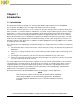
Table of Contents Chapter 1 Introduction 1.1 1.2 Introduction . . . . . . . . . . . . . . . . . . . . . . . . . . . . . . . . . . . . . . . . . . . . . . . . . . . . . . . . . . . . . . . . . 7 System Overview . . . . . . . . . . . . . . . . . . . . . . . . . . . . . . . . . . . . . . . . . . . . . . . . . . . . . . . . . . . . . 8 Chapter 2 Benefits and Features of the 9S12HZ256 Controller 2.1 2.2 2.3 2.3.1 2.3.2 Introduction . . . . . . . . . . . . . . . . . . . . . . . . . . . . . . . . . . . . . . .
Table of Contents Cluster (Dashboard) Using S12HZ256 as a Single-Chip Solution Designer Reference Manual, Rev.
Chapter 1 Introduction 1.1 Introduction This manual describes the design of a cluster board (dashboard) using Freescale’s S12HZ256 microcontroller unit (MCU). This is a single-chip design for the whole system. The traditional cluster board uses a cross coil motor to drive the analog pointers (actuator) which move either clockwise or counterclockwise to indicate the car speed, engine rotation speed, fuel level, engine temperature, etc. This technology is well established and widely used throughout the world.
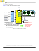
Introduction 1.2 System Overview Figure 1-1 provides a pictorial overview of the system. 5V Vcc Vreg * I/C0 Vehicle Speed Engine RPM Engine Temp. Batt.
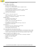
Chapter 2 Benefits and Features of the 9S12HZ256 Controller 2.1 Introduction As shown in this chapter, the S12HZ family of devices offers an excellent complement of peripherals and a broad range of memory and packages. 2.2 Basic Features Some of the S12HZ family benefits are shown below. Features have been broken down by type for your convenience.
Benefits and Features of the 9S12HZ256 Controller Analog-to-digital converter (ADC): • 16 channels, 10-bit resolution • External conversion trigger capability • Two 1M bit per second, CAN 2.
Modes of Operation Four stepper stall detectors (SSD): • Full step control during return to zero • Voltage selector and integrator/sigma delta converter circuit • 16-bit accumulator register • 16-bit modulus down counter 112-Pin LQFP and 80-Pin QFP packages: • 85 I/O lines with 5-V input and drive capability • 5-V A/D converter inputs • Eight key wake up interrupts with digital filtering and programmable rising/falling edge trigger • Operating speed: • Operation at 50 MHz equivalent to 25 MHz bus speed Dev
Benefits and Features of the 9S12HZ256 Controller Cluster (Dashboard) Using S12HZ256 as a Single-Chip Solution Designer Reference Manual, Rev.
Chapter 3 Stepper Motor Drive Theory 3.1 Introduction The stepper motor (MMT) is an excellent choice for cluster applications. This application employs high current drives suited for pulse width modulator (PWM) motor control, which supports sine and cosine drive, using the 9S12HZ256 device. Software running on the 9S12HZ256 device implements: • Micro-stepping to achieve precise linear position • Reduced noise • Vibration during stepper motor running. 3.
Stepper Motor Drive Theory 3.3 Stepper Motor Control Figure 3-1 shows a 2-phase step motor control signal. This signal switches on and off in turn and is driven by an H-bridge as shown in Figure 3-2. CCW CW A /A B /B A Store trip Figure 3-1. 2-Phase Step Motor Control Signal + A /A Supply - Phase A Figure 3-2. H-Bridge Cluster (Dashboard) Using S12HZ256 as a Single-Chip Solution Designer Reference Manual, Rev.
Stepper Motor Control As shown in Figure 3-3, phase A and B are driven by a square wave to move the rotor. It can be locked at a desired position when the phase supply (square wave) stops to alter. Rotate Gnd + Vdd Phase B - A Phase A Vdd Gnd Figure 3-3. Basic Driving Circuit for Two Phase Step Motor In order to drive a moving stepper motor, the S12H family offers a simple instruction to control step movement. The example below, uses motor channel 0 to control the stepper motor moving forward.
Stepper Motor Drive Theory Please refer to the firmware project (1. StepMove) for more detailed information. See Figure 3-4. Figure 3-4. StepMove Screen Cluster (Dashboard) Using S12HZ256 as a Single-Chip Solution Designer Reference Manual, Rev.
Stepper Motor Micro-Stepping Control 3.4 Stepper Motor Micro-Stepping Control The utility of micro-stepping is limited by at least three considerations. 1. Motor static friction 2. Non-sinusoidal character of the torque versus shaft-angle, each motor 3. Winding is quantized, controlled by a digital-to-analog converter (PWM) The most common control algorithm is adopted to use sinusoidal current to drive micro-stepping. One complete sinusoidal wave is equivalent to four steps in a 2-phase motor.
Stepper Motor Drive Theory Store trip + Supply /PWM PWM Phase Phase PWM /PWM A B Figure 3-6. Micro-Stepping Sinusoidal Control with PWM Please refer to the firmware project (2. MicroStepMove) for more detailed information. See Figure 3-7. Figure 3-7. MicroStepMove Screen Cluster (Dashboard) Using S12HZ256 as a Single-Chip Solution Designer Reference Manual, Rev.
Stepper Stall Detection (SSD) 3.5 Stepper Stall Detection (SSD) This module provides a built-in circuit to detect the induced voltage on the non-driven coil of a stepper motor. The back EMF can be measured by an internal ADC module, which can integrate the induced voltage on the non-driven coil, and store its results to a16-bit accumulator register. The internal 16-bit modulus down counter can be used to monitor the blanking time and the integration time.
Stepper Motor Drive Theory Please refer to the firmware project (3. StepperStallDetection) for more detailed information. See Figure 3-9. Figure 3-9. StepperStallDetection Screen Cluster (Dashboard) Using S12HZ256 as a Single-Chip Solution Designer Reference Manual, Rev.
LCD Driver for LCD Display Panel 3.6 LCD Driver for LCD Display Panel The S12HZ256 internal LCD driver module has 32 frontplane drivers and 4 backplane drivers. A maximum of 128 LCD segments are controllable. Each segment is controlled by a corresponding bit in the LCD RAM, located at address 0x120–0x137. Four multiplex modes (1/1, 1/2, 1/3, 1/4 duty) and three bias (1/1, 1/2, 1/3) methods are available.
Stepper Motor Drive Theory 3.7 LCD2 Panel Initialization and Checking In this reference design, the 4*18 segment LCD panel is selected. The LCD characters can be turned on/off by writing to the internal LCD registers, which are located at address 0x128–0x137. The LCD2.lib is also available for use. Users need to link to the LCD2.lib in their project. Please refer to the firmware project (5. LCD2DisplayCheck) for more detailed information. See Figure 3-12 and Figure 3-13. Figure 3-12.
LCD2 Panel Firmware (API) 3.8 LCD2 Panel Firmware (API) Users can use the API to display clock and mileage in the LCD2 panel. Examples are shown in Figure 3-14 and Figure 3-15. Please refer to LCD2DisplayEx project. Please refer to the firmware project (6. LCD2DisplayEx) for more detailed information. Figure 3-14. LCD2DisplayEx Screen Figure 3-15. API Testing for LCD2 Cluster (Dashboard) Using S12HZ256 as a Single-Chip Solution Designer Reference Manual, Rev.
Stepper Motor Drive Theory Cluster (Dashboard) Using S12HZ256 as a Single-Chip Solution Designer Reference Manual, Rev.
Chapter 4 Software Integration 4.1 Introduction The previous chapter explained several modules to drive individual application (stepper running in single step, micro-stepping control, LCD driver, motor stall detection, etc.). Now, we have to integrate those modules to implement a Cluster board application. It is a well-known fact that stepper motor vibration is commonly a drawback during motor running, although it only needs simple driving techniques.
Software Integration Please refer to the firmware project (7. MicroStepRamp) for detail. Figure 4-2. MicroStepRamp Screen Cluster (Dashboard) Using S12HZ256 as a Single-Chip Solution Designer Reference Manual, Rev.
Motor Running and LCD2 Panel Display Demonstration 4.3 Motor Running and LCD2 Panel Display Demonstration The demonstration code for Stepper Stall Detection (SSD), micro-stepping moving, and LCD2 panel display were done for the user reference. Please refer to MotorLCD2Demo project for details. The software flowchart is shown Figure 4-3.
Software Integration Please refer to the firmware project (8. MotorLCD2Demo) for more detailed information. Figure 4-4. MotorLCD2Demo Screen 4.
Cluster System Demonstration Start LCD2 Initialization for SSD Invoke SSD for 4 Motors Stepper Stall? No Yes Move to Home Position System Initialization Motors Movement Follow the Demo Sequence Display Mileage and Internal Clock to LCD2 No S1 Pressed? S2 Pressed? Yes Power On No S3 Pressed? Yes Store Trip Mileage to EEPROM Power Off No Demo On Yes Trip A/B selection S2 Held Over 1 Second? No Demo Off No S3 Pressed? Yes No Yes S1 Pressed? Selected Trip Clear Yes Figure 4-5.
Software Integration Please refer to the firmware project (9. ClusterDemo) for more detailed information. S1 S2 S3 S1 — Toggle Switch for Power On / Off S2 — Mileage Selection for Trip A, Trip B, and ODO S3 — Toggle Switch for Demo Figure 4-6. Cluster Demonstration Board Cluster (Dashboard) Using S12HZ256 as a Single-Chip Solution Designer Reference Manual, Rev.
Chapter 5 Hardware Schematics Detailed schematics for this reference design and provided in this chapter. Cluster (Dashboard) Using S12HZ256 as a Single-Chip Solution Designer Reference Manual, Rev.
Chapter 6 Bill of Materials Item Quantity Reference Part 1 3 C1, C10, C18 2 23 C2, C4, C6, C7, C8, C15, C17, C19, C20, C21, C22, C23, C24, C25, C26, C27, C28, C29, C30, C31, C32, C49, C50 3 3 C3, C9, C16 4 1 C5 5 8 C11, C12, C13, C14, C45, C46, C47, C48 6 2 C34, C33 10P 7 1 C39 100P 8 1 C40 0U003 10UF/25V 0U1 0U001 47UF/25V 10UF 9 1 C41 0U033 10 1 C42 0U047 11 3 C43, C44, C51 0U01 12 1 D1 13 10 D2, D7, D9, D11, D12, D13, D14, D15, D16, D17 14 1 D3 15 8
Bill of Materials Item Quantity 29 2 P2, P1 Reference Part 30 18 R1, R28, R30, R62, R63, R64, R65, R66, R67, R68, R71, R72, R73, R74, R75, R76, R77, R78 330 CON\DB9FR 31 2 R4, R2 510 32 1 R3 120 33 2 R18, R5 10K 34 14 R6, R7, R21, R29, R31, R32, R33, R34, R43, R46, R47, R48, R60, R61 47K 35 5 R9, R15, R23, R27, R59 1K 36 13 R19, R35, R36, R37, R38, R40, R41, R49, R50, R51, R52, R54, R55 4K7 37 1 R24 1K2 38 1 R25 100 39 4 R39, R42, R53, R56 1M 40 4 R44, R45,
How to Reach Us: Home Page: www.freescale.com E-mail: support@freescale.com USA/Europe or Locations Not Listed: Freescale Semiconductor Technical Information Center, CH370 1300 N. Alma School Road Chandler, Arizona 85224 +1-800-521-6274 or +1-480-768-2130 support@freescale.