
Reference guide


Stepper Motor Drive Theory
Cluster (Dashboard) Using S12HZ256 as a Single-Chip Solution Designer Reference Manual, Rev. 0
14 Freescale Semiconductor
3.3 Stepper Motor Control
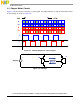
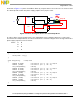
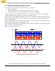
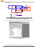
Figure 3-1 shows a 2-phase step motor control signal. This signal switches on and off in turn and is driven
by an H-bridge as shown in Figure 3-2.
Figure 3-1. 2-Phase Step Motor Control Signal
Figure 3-2. H-Bridge
A
/B
CW
CCW
B
/A
A
Store
tri
p
A
/A
Supply
+
-
Phase
A