
Reference guide


Stepper Motor Control
Cluster (Dashboard) Using S12HZ256 as a Single-Chip Solution Designer Reference Manual, Rev. 0
Freescale Semiconductor 15
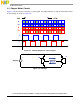
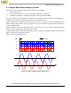
As shown in Figure 3-3, phase A and B are driven by a square wave to move the rotor. It can be locked
at a desired position when the phase supply (square wave) stops to alter.
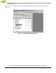
Figure 3-3. Basic Driving Circuit for Two Phase Step Motor
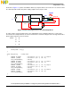
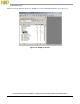
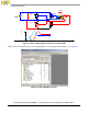
In order to drive a moving stepper motor, the S12H family offers a simple instruction to control step
movement. The example below, uses motor channel 0 to control the stepper motor moving forward. The
phase supply sequences are as follows:
Phase A B
01
00
10
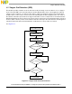
void eat_time(int time) //eat time
{
while(time--!=0){}
}
void step_move() //step move
{
MCDC0H &=~0x80; //channel 0 (A = 0, /A = 1) Step 0
MCDC1H |=0x80; //channel 1 (B = 1, /B = 0)
eat_time(0x2000); //delay
MCDC0H &=~0x80; //channel 0 (A = 0, /A = 1) Step 1
MCDC1H &=~0x80; //channel 1 (B = 0, /B = 1)
eat_time(0x2000); //delay
MCDC0H |=0x80; //channel 0 (A = 1, /A = 0) Step 2
MCDC1H &=~0x80; //channel 1 (B = 0, /B = 1)
eat_time(0x2000); //delay
MCDC0H |=0x80; //channel 0 (A = 1, /A = 0) Step 3
MCDC1H |=0x80; //channel 1 (B = 1, /B = 0)
eat_time(0x2000); //delay
}
A
Gnd
Vdd
+
-
Phase A
Vdd
Gnd
Phase B
Rotate