
Reference guide

Stepper Motor Micro-Stepping Control
Cluster (Dashboard) Using S12HZ256 as a Single-Chip Solution Designer Reference Manual, Rev. 0
Freescale Semiconductor 17
3.4 Stepper Motor Micro-Stepping Control
The utility of micro-stepping is limited by at least three considerations.
1. Motor static friction
2. Non-sinusoidal character of the torque versus shaft-angle, each motor
3. Winding is quantized, controlled by a digital-to-analog converter (PWM)
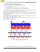
The most common control algorithm is adopted to use sinusoidal current to drive micro-stepping. One
complete sinusoidal wave is equivalent to four steps in a 2-phase motor.
Phase A is driven by a PWM as sinusoidal to move the rotor. It can also be locked at a desired position
when the phase supply stops to alter. The stepper motor can be held by the supply current from the driver
as static holding torque.
Phase A and B are driven by a sinusoidal wave to move the rotor. It can be locked at a desired position
when the phase supply (sinusoidal wave) stops to alter.
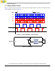
To drive stepper motor moving, the S12H family can use a simple look-up table to implement a sinusoidal
signal to drive micro-stepping movement.
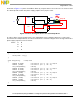
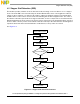
Refer to Figure 3-5 and Figure 3-6.
Figure 3-5. Micro-Stepping Sinusoidal Control
A
/B
CW
CCW
B
/A
A
S
t