
Reference guide


Stepper Stall Detection (SSD)
Cluster (Dashboard) Using S12HZ256 as a Single-Chip Solution Designer Reference Manual, Rev. 0
Freescale Semiconductor 19
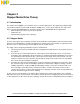
3.5 Stepper Stall Detection (SSD)
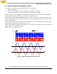
This module provides a built-in circuit to detect the induced voltage on the non-driven coil of a stepper
motor. The back EMF can be measured by an internal ADC module, which can integrate the induced
voltage on the non-driven coil, and store its results to a16-bit accumulator register. The internal 16-bit
modulus down counter can be used to monitor the blanking time and the integration time. The value in
the 16-bit accumulator represents the change in linked flux. It can be compared to a stored threshold to
distinguish whether the motor reaches the home position. Values above the threshold indicate a moving
motor, in which case the pointer can be advanced another full step in the same direction and integration
repeated. Values below the threshold indicate a stalled motor, home position is reached.
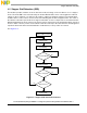
See Figure 3-8.
Figure 3-8. Stepper Stall Detection Flowchart
Advanced Motor Pointer
Initialized SSD
Start Blinking
No
End of Start Blinking
Yes
Start Integration
End of Integration
No
Yes
No
Stall Detection
Disabled SSD