
Reference guide


Cluster (Dashboard) Using S12HZ256 as a Single-Chip Solution Designer Reference Manual, Rev. 0
Freescale Semiconductor 25
Chapter 4
Software Integration
4.1 Introduction
The previous chapter explained several modules to drive individual application (stepper running in single
step, micro-stepping control, LCD driver, motor stall detection, etc.). Now, we have to integrate those
modules to implement a Cluster board application. It is a well-known fact that stepper motor vibration is
commonly a drawback during motor running, although it only needs simple driving techniques. Thus,
micro-stepping is a typical solution when a stepper motor is chosen in an application. In addition, we also
need to overcome stepper motor inertia, which plays an important role in driving motor starting smoothly.
4.2 Micro-Stepping Control Using Internal Timer
The gauge pointer is driven by a stepper motor, which can directly reflect how good the Cluster
performance is. Thus, some control parameters may be beneficial when introduce in stepper motor
control, such as acceleration and maximum velocity even in micro-stepping. The acceleration and
maximum velocity parameters can be done by the S12HZ256 internal 16-bit timer module. In this
reference design, the acceleration can be pre-calculated as a lookup table (StepProfileBase[]), which is
stored in the internal Flash. It can also be retrieved from internal Flash to internal RAM for run time
modification in different speed profiles. The maximum speed setting can also prevent the motor from
running beyond the limit.
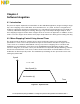
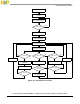
Figure 4-1. Speed Profile
Speed
Time
Max Speed (v)
A
cceleration (a)
v = u + at