UM10533 TEA1723BT GreenChip SP low standby power SMPS demo board Rev. 1 — 21 May 2012 User manual Document information Info Content Keywords TEA1723BT, ultra-low standby power, constant output voltage, constant output current, primary sensing, integrated high-voltage switch, integrated high-voltage start-up, tablet charger, 5 V/2.1 A supply Abstract This user manual describes an 11 W Constant Voltage/Constant Current (CV/CC) universal input power supply for tablet adapters/chargers.
UM10533 NXP Semiconductors TEA1723BT GreenChip SP SMPS demo board Revision history Rev Date Description v.1 20120521 first issue Contact information For more information, please visit: http://www.nxp.com For sales office addresses, please send an email to: salesaddresses@nxp.com UM10533 User manual All information provided in this document is subject to legal disclaimers. Rev. 1 — 21 May 2012 © NXP B.V. 2012. All rights reserved.
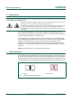
UM10533 NXP Semiconductors TEA1723BT GreenChip SP SMPS demo board 1. Introduction WARNING Lethal voltage and fire ignition hazard The non-insulated high voltages that are present when operating this product, constitute a risk of electric shock, personal injury, death and/or ignition of fire. This product is intended for evaluation purposes only.
UM10533 NXP Semiconductors TEA1723BT GreenChip SP SMPS demo board 3.
UM10533 NXP Semiconductors TEA1723BT GreenChip SP SMPS demo board a. Top view. b. Bottom view. Fig 2. UM10533 User manual TEA1723BT 11 W demo board All information provided in this document is subject to legal disclaimers. Rev. 1 — 21 May 2012 © NXP B.V. 2012. All rights reserved.
UM10533 NXP Semiconductors TEA1723BT GreenChip SP SMPS demo board 5. Performance data 5.1 No-load input power consumption Test condition: The no-load input power is measured after a 20 minute warm-up time. Table 2. No-load input power consumption Condition Output voltage Power consumption 115 V at 60 Hz 5V 23 mW 230 V at 50 Hz 5V 25.6 mW DDD 1R ORDG SRZHU P: Fig 3. ,QSXW 9ROWDJH 9 No-load input power consumption 5.
UM10533 NXP Semiconductors TEA1723BT GreenChip SP SMPS demo board DDD 9RXW 9 ORXW $ (1) 90 V. (2) 115 V. (3) 230 V. (4) 265 V. Fig 4. VI characteristics at 90 V, 115 V, 230 V and 265 V DDD Ș ORXW $ (1) Efficiency at 115 V. (2) Efficiency at 230 V. Fig 5. Efficiency at 115 V and 230 V 5.3 Dynamic loading from 0 A to 0.
UM10533 NXP Semiconductors TEA1723BT GreenChip SP SMPS demo board The load step is measured at Vmains = 230 V and the output capacitors C5/C6 are 2 470 F. The burst frequency is 885 Hz. (1) CH1 = VDRAIN. (2) CH2 = IO. (3) CH3 = VO. Fig 6. Load step from 0 A to 0.5 A 5.4 Dynamic loading from 0.5 A to 0 A Test condition: The dynamic loading is tested at a load step of 0 A to 0.5 A. The TEA1723BT detects the load step only after the next switching cycle because of the primary sensing feature.
UM10533 NXP Semiconductors TEA1723BT GreenChip SP SMPS demo board (1) CH1 = VDRAIN. (2) CH2 = IO. (3) CH3 = VO. Fig 7. Load step from 0.5 A to 0 A After the load step 0.5 A to 0 A, the output voltage rises to 5.1 V. The transition takes about 1 ms when the controller switches from CV to CVB because of the large electrolytic output capacitors (2 470 µF). 5.5 Short-circuit of the output The demo board output can be short-circuited without damaging of any component.
UM10533 NXP Semiconductors TEA1723BT GreenChip SP SMPS demo board (1) CH1 = VDRAIN. (2) CH2 = VCC. (3) CH3 = IO. (4) CH4 = VO. Fig 8. Short-circuit of the output 5.6 Output voltage ripple performance Test condition: Output voltage ripple is measured using an oscilloscope probe connected to the demo board output. A probe tip was used with a very small GND connection. A 100 nF capacitor between output voltage and GND is used to reduce high frequency noise.
UM10533 NXP Semiconductors TEA1723BT GreenChip SP SMPS demo board (1) CH1 = VDRAIN. (2) CH4 = VO on board. Scale = 100 mV/division. Fig 9. Output voltage ripple 5.7 Conducted EMI measurement results The EMI is measured with the secondary GND connected to the protected mains earth GND. Y-capacitor (C10 = 2.2 nF; 2 kV) is added and only one input coil L1 = 1.5 mH is used. EMI is measured on the neutral phase and on the line phase at Vmains = 230 V and at full load.
UM10533 NXP Semiconductors TEA1723BT GreenChip SP SMPS demo board Remark: Improved transformer design will enhance TEA1723BT EMI performance significantly. Fig 10. Line 230 V, full load and negative output connected to protected earth Remark: Improved transformer design will enhance TEA1723BT EMI performance significantly. Fig 11. Neutral 115 V, full load and negative output connected to protected earth UM10533 User manual All information provided in this document is subject to legal disclaimers.
UM10533 NXP Semiconductors TEA1723BT GreenChip SP SMPS demo board Remark: Improved transformer design will enhance TEA1723BT EMI performance significantly. Fig 12. Line 115 V, full load and negative output connected to protected earth Remark: Improved transformer design will enhance TEA1723BT EMI performance significantly. Fig 13. Neutral 230 V, full load and negative output connected to protected earth UM10533 User manual All information provided in this document is subject to legal disclaimers.
UM10533 NXP Semiconductors TEA1723BT GreenChip SP SMPS demo board 6. Schematic and Bill Of Materials (BOM) 6.
UM10533 NXP Semiconductors TEA1723BT GreenChip SP SMPS demo board Table 4. Bill of materials …continued Part Description D8 diode; SBR10U45SP5; 45 V; PowerDI5; 10 A SBR10U45SP5-13 Diodes Inc IC1 controller; TEA1723BT; S07 TEA1723BT NXP Semiconductors L1 inductor; 1.5 mH; DIP - Murata R1 resistor; 10 k; 1206 - - R3 resistor; 100 k; 1206 - - R4 resistor; 180 ; 1206 - - R5 resistor; 2.4 ; 1206 - - R6 resistor; 12 ; 0805 - - R7 resistor; 5.
UM10533 NXP Semiconductors TEA1723BT GreenChip SP SMPS demo board 7. Circuit description The TEA1723BT GreenChip SP demo board consists of a single-phase full-wave rectifier circuit with sections for filtering, switching, output and feedback. The circuit diagram is shown in Figure 14 on page 14 and the component list is shown in Table 4 on page 14. 7.1 Rectification section The bridge diodes BD1 form the single-phase full-wave rectifier.
UM10533 NXP Semiconductors TEA1723BT GreenChip SP SMPS demo board 8. PCB layout Figure 16 shows the layout of the PCB. a. Top silk b. Bottom silk c. Bottom layer Fig 15. Board layout UM10533 User manual All information provided in this document is subject to legal disclaimers. Rev. 1 — 21 May 2012 © NXP B.V. 2012. All rights reserved.
UM10533 NXP Semiconductors TEA1723BT GreenChip SP SMPS demo board 9. Transformer specifications 9.1 Transformer schematic design and winding construction The transformer used in the TEA1723BT demo board has size EE20 with bobbin EE20/10/6 horizontal, 14-pin. The secondary side of the transformer is connected in parallel in the TEA1723BT demo board, see Figure 16.
UM10533 NXP Semiconductors TEA1723BT GreenChip SP SMPS demo board 9.3 Core, air gap and bobbin • Core: EE20/10/6 (3C90) • Size of the air gap depends on the AL value of the ungapped core. • Bobbin: EE20/10/6 horizontal, 14-pin DDD Fig 17. EE20/10/6 bobbin footprint UM10533 User manual All information provided in this document is subject to legal disclaimers. Rev. 1 — 21 May 2012 © NXP B.V. 2012. All rights reserved.
UM10533 NXP Semiconductors TEA1723BT GreenChip SP SMPS demo board 10. Attention points When testing the CC mode of the TEA1723BT, use an electronic DC-load in resistive mode, not in current mode. The current in CC mode has a small fold back characteristic (see Figure 4). When current mode of an electronic DC-load is used, the output voltage drops immediately to zero when the maximum current is exceeded.
UM10533 NXP Semiconductors TEA1723BT GreenChip SP SMPS demo board 11.
UM10533 NXP Semiconductors TEA1723BT GreenChip SP SMPS demo board 12. Legal information 12.1 Definitions Draft — The document is a draft version only. The content is still under internal review and subject to formal approval, which may result in modifications or additions. NXP Semiconductors does not give any representations or warranties as to the accuracy or completeness of information included herein and shall have no liability for the consequences of use of such information. 12.
UM10533 NXP Semiconductors TEA1723BT GreenChip SP SMPS demo board 13. Contents 1 2 3 4 5 5.1 5.2 5.3 5.4 5.5 5.6 5.7 6 6.1 6.2 7 7.1 7.2 7.3 7.4 7.5 8 9 9.1 9.2 9.3 10 11 12 12.1 12.2 12.3 13 Introduction . . . . . . . . . . . . . . . . . . . . . . . . . . . . 3 Safety Warning. . . . . . . . . . . . . . . . . . . . . . . . . . 3 TEA1723BT features . . . . . . . . . . . . . . . . . . . . . 4 Technical specification . . . . . . . . . . . . . . . . . . . 4 Performance data. . . . . . . . . . . . . . . . .