
User guide


UM10533 All information provided in this document is subject to legal disclaimers. © NXP B.V. 2012. All rights reserved.
User manual Rev. 1 — 21 May 2012 9 of 23
NXP Semiconductors
UM10533
TEA1723BT GreenChip SP SMPS demo board
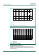
After the load step 0.5 A to 0 A, the output voltage rises to 5.1 V. The transition takes
about 1 ms when the controller switches from CV to CVB because of the large electrolytic
output capacitors (2 470 µF).
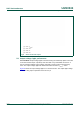
5.5 Short-circuit of the output
The demo board output can be short-circuited without damaging of any component.
Test condition: Figure 7
shows the converter behavior when the output is short-circuited.
During a short-circuit of the output, the VCC voltage (CH3) switches between
V
CC(startup)
= 17 V and V
CC(stop)
= 8.5 V levels. The average output current during
converter switching is 1.2 A.
(1) CH1 = V
DRAIN
.
(2) CH2 = I
O
.
(3) CH3 = V
O
.
Fig 7. Load step from 0.5 A to 0 A