INTEGRATED CIRCUITS DATA SHEET TJA1040 High speed CAN transceiver Product specification Supersedes data of 2003 Feb 19 2003 Oct 14
Philips Semiconductors Product specification High speed CAN transceiver TJA1040 FEATURES GENERAL DESCRIPTION • Fully compatible with the ISO 11898 standard The TJA1040 is the interface between the Controller Area Network (CAN) protocol controller and the physical bus. It is primarily intended for high speed applications, up to 1 MBaud, in passenger cars. The device provides differential transmit capability to the bus and differential receive capability to the CAN controller.
Philips Semiconductors Product specification High speed CAN transceiver TJA1040 BLOCK DIAGRAM VCC handbook, full pagewidth 3 TXD TIME-OUT & SLOPE 1 TEMPERATURE PROTECTION V SPLIT VCC 5 7 6 STB RXD GND 8 WAKE-UP MODE CONTROL 4 SPLIT CANH CANL DRIVER WAKE-UP FILTER MUX TJA1040 2 MGU161 Fig.1 Block diagram.
Philips Semiconductors Product specification High speed CAN transceiver TJA1040 to the centre tap of the split termination (see Fig.4). In case of a recessive bus voltage <0.5VCC due to the presence of an unsupplied transceiver in the network with a significant leakage current from the bus lines to ground, the split circuit will stabilize this recessive voltage to 0.5VCC.
Philips Semiconductors Product specification High speed CAN transceiver TJA1040 LIMITING VALUES In accordance with the Absolute Maximum Rating System (IEC 60134). SYMBOL VCC PARAMETER supply voltage CONDITIONS MIN. MAX. UNIT no time limit −0.3 +6 V operating range 4.75 5.25 V VTXD DC voltage on pin TXD −0.3 VCC + 0.3 V VRXD DC voltage on pin RXD −0.3 VCC + 0.3 V VSTB DC voltage on pins STB −0.3 VCC + 0.3 V VCANH DC voltage on pin CANH 0 < VCC < 5.
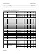
Philips Semiconductors Product specification High speed CAN transceiver TJA1040 CHARACTERISTICS VCC = 4.75 to 5.25 V, Tvj = −40 to +150 °C and RL = 60 Ω unless specified otherwise; all voltages are defined with respect to ground; positive currents flow into the IC; note 1. SYMBOL PARAMETER CONDITIONS MIN. TYP. MAX. UNIT Supply (pin VCC) ICC supply current 5 10 15 µA recessive; VTXD = VCC 2.
Philips Semiconductors Product specification High speed CAN transceiver SYMBOL PARAMETER VO(reces) recessive output voltage IO(sc) short-circuit output current TJA1040 CONDITIONS MIN. normal mode; VTXD = VCC; 2 no load standby mode; no load TYP. MAX. UNIT 0.5VCC 3 V −0.1 0 +0.1 V −40 −70 −95 mA VTXD = 0 V pin CANH; VCANH = 0 V pin CANL; VCANL = 40 V 40 70 100 mA − +2.5 mA normal mode (see Fig.6) 0.5 0.7 0.9 V standby mode 0.4 0.7 1.
Philips Semiconductors Product specification High speed CAN transceiver TJA1040 APPLICATION AND TEST INFORMATION handbook, full pagewidth 5V BAT VCC CANH 3 7 8 STB Port x VCC TJA1040 SPLIT MICROCONTROLLER 5 4 CANL 6 2 1 RXD TXD RXD TXD MGU164 More application information is available in a separate application note. Fig.3 Typical application for 5 V microcontroller. VCC handbook, full pagewidth TJA1040 CANH 60 Ω R VSPLIT = 0.
Philips Semiconductors Product specification High speed CAN transceiver handbook, full pagewidth TJA1040 +5 V 47 µF 100 nF VCC TXD 3 1 7 TJA1040 500 kHz RXD CANL 1 nF 1 nF TRANSIENT GENERATOR SPLIT 5 4 2 15 pF 6 CANH 8 GND STB MGW336 The waveforms of the applied transients will be in accordance with ISO 7637 part 1, test pulses 1, 2, 3a, 3b, 5, 6 and 7. Fig.5 Test circuit for automotive transients. handbook, full pagewidth MGS378 VRXD HIGH LOW hysteresis 0.5 0.9 Fig.
Philips Semiconductors Product specification High speed CAN transceiver handbook, full pagewidth TJA1040 +5 V 47 µF 100 nF VCC TXD 3 1 7 SPLIT RXD CANH RL 60 Ω TJA1040 5 6 CANL CL 100 pF 4 2 15 pF 8 GND STB MGW335 Fig.7 Test circuit for timing characteristics. handbook, full pagewidth HIGH TXD LOW CANH CANL dominant (BUS on) 0.9 V Vi(dif)(bus) (1) 0.5 V recessive (BUS off) HIGH RXD 0.7VCC 0.
Philips Semiconductors Product specification High speed CAN transceiver TJA1040 BONDING PAD LOCATIONS COORDINATES(1) SYMBOL PAD x y 119.5 114.5 TXD 1 GND 2 648.5 85 VCC 3 1214.25 114.5 RXD 4 1635.25 114.5 SPLIT 5 1516.5 1275 CANL 6 990.5 1273.75 CANH 7 530.25 1273.75 STB 8 113.75 1246 7 6 5 test pad 1 TJA1040U test pad 2 x 0 1 0 2 3 4 y Note MBL584 The backside of the bare die must be connected to ground. 1.
Philips Semiconductors Product specification High speed CAN transceiver TJA1040 PACKAGE OUTLINE SO8: plastic small outline package; 8 leads; body width 3.9 mm SOT96-1 D E A X c y HE v M A Z 5 8 Q A2 A (A 3) A1 pin 1 index θ Lp 1 L 4 e detail X w M bp 0 2.5 5 mm scale DIMENSIONS (inch dimensions are derived from the original mm dimensions) UNIT A max. A1 A2 A3 bp c D (1) E (2) e HE L Lp Q v w y Z (1) mm 1.75 0.25 0.10 1.45 1.25 0.25 0.49 0.36 0.25 0.19 5.
Philips Semiconductors Product specification High speed CAN transceiver TJA1040 To overcome these problems the double-wave soldering method was specifically developed. SOLDERING Introduction to soldering surface mount packages If wave soldering is used the following conditions must be observed for optimal results: This text gives a very brief insight to a complex technology.
Philips Semiconductors Product specification High speed CAN transceiver TJA1040 Suitability of surface mount IC packages for wave and reflow soldering methods SOLDERING METHOD PACKAGE(1) WAVE BGA, LBGA, LFBGA, SQFP, SSOP-T(3), TFBGA, VFBGA not suitable suitable(4) DHVQFN, HBCC, HBGA, HLQFP, HSQFP, HSOP, HTQFP, HTSSOP, HVQFN, HVSON, SMS not PLCC(5), SO, SOJ suitable REFLOW(2) suitable suitable suitable not recommended(5)(6) suitable SSOP, TSSOP, VSO, VSSOP not recommended(7) suitable PMFP
Philips Semiconductors Product specification High speed CAN transceiver TJA1040 DATA SHEET STATUS LEVEL DATA SHEET STATUS(1) PRODUCT STATUS(2)(3) Development DEFINITION I Objective data II Preliminary data Qualification This data sheet contains data from the preliminary specification. Supplementary data will be published at a later date. Philips Semiconductors reserves the right to change the specification without notice, in order to improve the design and supply the best possible product.
Philips Semiconductors Product specification High speed CAN transceiver TJA1040 Bare die All die are tested and are guaranteed to comply with all data sheet limits up to the point of wafer sawing for a period of ninety (90) days from the date of Philips' delivery. If there are data sheet limits not guaranteed, these will be separately indicated in the data sheet. There are no post packing tests performed on individual die or wafer.
Philips Semiconductors – a worldwide company Contact information For additional information please visit http://www.semiconductors.philips.com. Fax: +31 40 27 24825 For sales offices addresses send e-mail to: sales.addresses@www.semiconductors.philips.com. SCA75 © Koninklijke Philips Electronics N.V. 2003 All rights are reserved. Reproduction in whole or in part is prohibited without the prior written consent of the copyright owner.