
Datasheet


2003 Oct 14 6
Philips Semiconductors Product specification
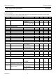
High speed CAN transceiver TJA1040
CHARACTERISTICS
V
CC
= 4.75 to 5.25 V, T
vj
= −40 to +150 °C and R
L
=60Ω unless specified otherwise; all voltages are defined with
respect to ground; positive currents flow into the IC; note 1.
SYMBOL PARAMETER CONDITIONS MIN. TYP. MAX. UNIT
Supply (pin V
CC
)
I
CC
supply current standby mode 5 10 15 µA
normal mode
recessive; V
TXD
=V
CC
2.5 5 10 mA
dominant; V
TXD
=0V305070mA
Transmit data input (pin TXD)
V
IH
HIGH-level input voltage 2 − V
CC
+ 0.3 V
V
IL
LOW-level input voltage −0.3 − +0.8 V
I
IH
HIGH-level input current V
TXD
=V
CC
−50 +5µA
I
IL
LOW-level input current normal mode; V
TXD
=0V −100 −200 −300 µA
C
i
input capacitance not tested − 510pF
Standby mode control input (pin STB)
V
IH
HIGH-level input voltage 2 − V
CC
+ 0.3 V
V
IL
LOW-level input voltage −0.3 − +0.8 V
I
IH
HIGH-level input current V
STB
=V
CC
− 0 −µA
I
IL
LOW-level input current V
STB
=0V −1 −4 −10 µA
Receive data output (pin RXD)
V
OH
HIGH-level output voltage standby mode;
I
RXD
= −100 µA
V
CC
− 1.1 V
CC
− 0.7 V
CC
− 0.4 V
I
OH
HIGH-level output current normal mode;
V
RXD
=V
CC
− 0.4 V
−0.1 −0.4 −1mA
I
OL
LOW-level output current V
RXD
= 0.4 V 2 6 12 mA
Common-mode stabilization output (pin SPLIT)
V
O
output voltage normal mode;
−500 µA<I
O
< +500 µA
0.3V
CC
0.5V
CC
0.7V
CC
V
I
L
leakage current standby mode;
−22V<V
SPLIT
< +35 V
− 05µA
Bus lines (pins CANH and CANL)
V
O(dom)
dominant output voltage V
TXD
=0V
pin CANH 3 3.6 4.25 V
pin CANL 0.5 1.4 1.75 V
V
O(dom)(m)
matching of dominant output
voltage (V
CC
-V
CANH
-V
CANL
)
−100 0 +150 mV
V
O(dif)(bus)
differential bus output voltage
(V
CANH
− V
CANL
)
V
TXD
= 0 V; dominant;
45 Ω <R
L
<65Ω
1.5 − 3.0 V
V
TXD
=V
CC
; recessive;
no load
−50 − +50 mV