
Daim Ntawv Qhia Tus Neeg Siv
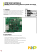
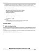
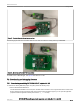
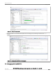
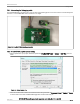
Table Of Contents

The NXP MWPR1516 chip is the central controller of the WPR1500-HV receiver board. The chip higher integration receiver
controller MCU for wireless power transfer application. The WPR15xx is a Cortex M0+ core ASSP with NXP’s UHV
technology. It includes the FSK and CNC models that allow easy development for bi-directional communication architecture
between the transmitter and receiver.
The following modules are used in this application:
— CNC controls the communication and provides AC protection.
— High-voltage input PMC module with three power modes: Run, Wait, Stop.
— Programmable gain amplifier (PGA) with differential input and output.
— FSK demodulation timer (FSKDT).
— WDOG with independent clock source.
• Rectifier
The rectifier uses a self-driven sync type. Its characteristics are:
— Input voltage: 3.5 V - 20 V AC peak.
— Output voltage: 3.5 V - 20 V DC.
• Communication
— The ASK differential bi-phase signal is modulated by switching the modulation capacitor.
— The FSK signal is demodulated by the CNC and FSKDT module.
7 Getting Started
7.1 System developing environment
WPR1500-HV receiver board supports debugging with IAR and FreeMASTER tools. The following figure shows the setup of the
debug connection. To download an image onto the WPR1516 chip, connect a debugger (J-LINK or P&E-Multilink FX) to the JTAG
port of the receiver board. J3 (V_REC) and J5 (GND) on the board need to be connected to 5 - 12 V DC power supply in order to
get power.
To monitor the working status of the WPR1500-HV receiver board by FreeMASTER, remove the external power before putting
the WPR1500-HV receiver board on the transmitter panel.
The following figure shows the connection when downloading an image.
NXP Semiconductors
Getting Started
WPR1500-HV Wireless Charging Receiver Application User’s Guide, Rev. 3.0, 4 July 2022
User Guide 4 / 17