It is of vital importance, before attempting to operate your engine, to read the general 'SAFETY INSTRUCTIONS AND WARNINGS' section on pages 2-3 of this booklet and to strictly adhere to the advice contained therein. • Also, please study the entire contents of • • this instruction manual, so as to familiarize yourself with the controls and other features of the engine. Keep these instructions in a safe place so that you may readily refer to them whenever necessary.
CONTENTS SAFETY INSTRUCTIONS AND WARNINGS ABOUT YOUR O.S.
SAFETY INSTRUCTIONS AND WARNINGS ABOUT YOUR O.S. ENGINE WARNINGS • Never touch, or allow any object to come Remember that your engine is not a " toy ", but a highly efficient internal-combustion machine whose power is capable of harming you, or others, if it is misused. As owner, you, alone, are responsible for the safe operation of your engine, so act with discretion and care at all times. If at some future date, your O.S.
NOTES ● This engine was designed for model boats. Do not attempt to use it for any other purpose. ● Mount the engine in your model securely, following the manufacturers' recommendations, using appropriate screws and locknuts. ● Fit an effective silencer(muffler). Frequent close exposure to a noisy exhaust (especially in the case of the most powerful highspeed engines) may eventually impair your hearing and such noise is also likely to cause annoyance to others over a wide area.
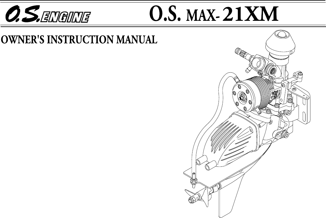
The O.S. MAX-21XM is a high-performance water-cooled outboard marine engine for small and medium-size radio-controlled outboard boats. It is of sturdy construction and designed for easy maintenance. It is not necessary to readjust the linkage when the installation angle to the hull is changed. A tilt mount is supplied as standard. Also, a carbon-fibre propeller is included.
BASIC ENGINE PARTS Flywheel(OS No.
LINKAGES PIPING Steering Linkage Use a high-torque servo, preferably with dual pushrods as shown below.(A single pushrod will bend easily which results in poor steering accuracy.) Connect the water inlet tube (L=170mm) and oil transfer pipe (L=65mm) securely as shown on page 5. In the event of either tube becoming damaged, it should be replaced with best quality 5.5mm OD✕2.5mm ID silicone tubing. Note : When cutting silicone tubing..... Steering Servo Silicone tubing Use knife or razor blade.
Reminder! Secure Linkage Bracket Model engine fuel is poisonous. Do not allow it to come into contact with the eyes or mouth. Always store it in a clearly marked container and out of the reach of children. 3mm OD Outer Pipe Model engine fuel is also highly flammable. Keep it away from naked flame, excessive heat, sources of sparks, or anything else which might ignite it. Do not smoke, or allow anyone else to smoke, near to it.
● ● ● 2. Remove the flexible drive shaft and its sleeve and if any debris is found in the sleeve, wash it out with fuel or alcohol before greasing the full length of the new shaft and reinserting it into the sleeve. Fit a plug suitable for the engine (e.g. OS No.8). Use fuel containing a moderate percentage of nitromethane unless essential for racing events. Do not run the engine too lean and do not leave the battery connected while adjusting the needle. 3.
● Before starting the engine for the first run of the day, remove the glowplug and check the engine by rotating the flywheel by hand. It should rotate smoothly. Now turn the engine with an electric starter until fuel is drawn into the carburettor. At first, rotation may feel 'sticky' due to oily residue remaining within the engine. The engine should rotate freely after fresh mixture has been drawn into the working parts. ● Check the glowplug.
◆ Heat the glowplug by connecting the battery leads. Mixture Control Valve (Mixture Control Screw) Nozzle ◆ Make sure that the direction of rotation of the electric starter is correct, namely, clockwise. If necessary, reverse leads on battery to provide clockwise rotation. Clockwiserotation ◆ Bring the starter into contact with the flywheel and depress the starter switch for one or two seconds. Repeat if necessary. When the engine fires, withdraw the starter immediately.
3. It is necessary to warm up the engine by running it at around the idling setting for a while after starting, as with the engine of a full size boat. High r.p.m. operation without warming up will shorten engine life or damage it. RUNNING-IN (''Breaking-in'') For long life and high-performance, every engine needs to be properly 'run-in' or 'broken-in'. There are several running-in methods, but the following is suitable for use with the MAX21XM. 4.
5. Aim to have the model achieving its highest performance after the engine has consumed about one litre of fuel. Having found the optimum needle-valve setting, make a note of the number of turns necessary to re-establish this from the closed position. ADJUSTMENT WARNING : Running the engine with the boat out of the water, without load and without cooling water, will seriously damage it, due to overheating.
9. With the optimum mixture control valve position, light smoke is visible during high-speed running and engine revolutions increase smoothly during acceleration. Remember that, if the engine is operated with the fuel/air mixture slightly too lean, it will overheat and run unevenly or cut out. As with all engines, it is wise to set both valves a little on the rich side of the best rpm setting, as a safety measure.
To reduce such risks, it is helpful to inject some corrosion inhibiting oil into the engine's air intake. Rotate the engine many times to distribute the oil to all the working parts. CARE AND MAINTENANCE To ensure that you obtain long life and peak performance from your engine, observe the follow-ing. 4 Drain the water remaining in the water cooling head, and wash out with methanol, then inject corrosion-inhibiting or moisture-displacing oil.
TROUBLE SHOOTING WHEN THE ENGINE FAILS TO START Four key points For quick, reliable starting, the following four conditions are required. 1 Good compression. 2 Adequate "glow" at glowplug. 3 Correct mixture. 4 Sufficient electric starter rotating speed. If the engine fails to start, or does not keep running after being started, check symptoms against the following chart and take necessary corrective action.
EXPLODED VIEW 1-1 N.+M3X10 23-F N.+M4X8 1 C.M3X12 23-G 2 13-3 N.M3X10 C.M2.6X18 C.M4X12 23-C1 3 4 23-C 6 11 23-J 5 23-C2 11-1 23-H 9 13 N.M3X12 7 14 23-I 8 C.M2.6X18 10 15 C.M4X12 23-L 16 24 F.M3X8 13-1 17 13-2 23-K F.M3X10 23-B 25 12 18 C.M2.6X10 23-D 19 C.M3X10 23-A 23-E 20 23-M 21 22 C.M2.
PARTS LIST No. Code No. 1 7 1802 100 1-1 2 7721 700 Description Flywheel Assembly (No.2J) Flywheel Nut Description No. Code No. 19 2 3871 130 Outboard Unit Fixing Screw (4pcs.
CARBURETTOR EXPLODED VIEW & PARTS LIST S.3X3 1-1 1 2 5 6 4 7 3-1 3 S.3X3 8-5 9 8-3 8-2 8-4 8-1 8 No. Code No. 1 2 4981 405 1-1 2 6381 501 2 2 5381 203 Carburettor Rotor 3 2 6781 309 Mixture Control Valve 3-1 2 4881 824 4 2 6781 506 5 6 No. Code No. 7 2 2681 953 Fuel Inlet 8 2 7881 900 Needle Valve Assembly 8-1 2 4981 959 Needle 8-2 2 4981 837 '' O '' Ring (2pcs.
THREE VIEW DRAWING 46 3.46 c.c. ( 0.211 cu.in.) 16.6 mm ( 0.654 in.) 16.0 mm ( 0.630 in.) 3,000~25,000 r.p.m. 1.3 bhp / 25,000r.p.m. 670g ( 23.6 oz.) 46 219 34.5 45 37.5 25 87 Displacement Bore Stroke Practical R.P.M. Power output Weight 48.5 86 46 ■ ■ ■ ■ ■ ■ 64 48.5 SPECIFICATION 149.
MEMO 20
Q U A LIT Y PRECISION & P ERFO RM AN NC E UN ES LED CE UAL EQ T AB L IS H IN G T H E STA N D A R D S O F EXCE LLE 6-15 3-Chome Imagawa Higashisumiyoshi-ku Osaka 546-0003, Japan TEL. (06) 6702-0225 FAX. (06) 6704-2722 URL : http://www.os-engines.co.jp C Copyright 2000 by O.S.Engines Mfg. Co., Ltd. All rights reserved. Printed in Japan.