It is of vital importance, before attempting to operate your engine, to read the general 'SAFETY INSTRUCTIONS AND WARNINGS' section on pages 2-6 of this booklet and to strictly adhere to the advice contained therein. Also, please study the entire contents of this instruction manual, so as to familiarize yourself with the controls and other features of the engine. Keep these instructions in a safe place so that you may readily refer to them whenever necessary.
SAFETY INSTRUCTIONS AND WARNINGS ABOUT YOUR O.S. ENGINE Remember that your engine is not a "toy", but a highly efficient internalcombustion machine whose power is capable of harming you, or others, if it is misused. As owner, you, alone, are responsible for the safe operation of your engine, so act with discretion and care at all times. If at some future date, your O.S. engine is acquired by another person, we would respectfully request that these instructions are also passed on to its new owner.
NOTES This engine was designed for model aircraft. Do not attempt to use it for any other purpose. If you remove the glowplug from the engine and check its condition by connecting the battery leads to it, do not hold the plug with bare fingers.Use an appropriate tool or a folded piece of cloth. Mount the engine in your model securely, following the manufacturers' recommendations, using appropriate screws and locknuts.
NOTES Adjust the throttle linkage so that the engine stops when the throttle stick and trim lever on the transmitter are fully retarded. Alternatively, the engine may be stopped by cutting off the fuel supply. Never try to stop the engine physically. For their safety, keep all onlookers (especially small children) well back (at least 20 feet or 6 meters) when preparing your model for flight. If you have to carry the model to the take-off point with the engine running, be especially cautious.
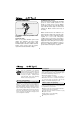
Features Since this is a rotary engine designed for model application, there are some notes to be followed in order to run it well for a long time. Also, handling of this engine is somewhat different from that of two-stroke and four-stroke engines.
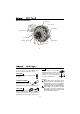
BASIC ENGINE PARTS Front Housing Rotor Housing Engine Mount RE-2010 Silencer Air Funnel Glowplug TypeF Carburetor Type 21G Drive Hub Propeller washer Propeller nut 10 FUEL BEFORE STARTING Tools, accessories, etc. The following items are necessary for operating the engine. For this engine, use top quality methanol-based model engine fuel containing more than 18% oil either synthetic or castor and between 5% and 15% nitromethane. GLOW PLUG O.S. TypeF glowplug is supplied with the engine.
Electric Starter and Starter Battery O.S. Non-Bubble Weight S Electric Starter The engine is supplied with a small sized Non-Bubble Weight. Be sure to use it in a fuel tank installed in a model. Required when starting 12-Volt lead-acid battery the engine. Fuel Filter Since the distance from the carburetor to the expansion chamber in the housing is very short with a rotary engine, even a tiny bubble from the fuel tank will cause engine breathing. The Non-Bubble Weight will prevent from sucking bubbles.
Warning: Make sure that the propeller is well balanced. An unbalanced propeller and/or spinner can cause serious vibration which may weaken parts of the airframe or affect the safety of the radio-controlled system. DO NOT forget the WARNINGS and NOTES on propeller and spinner safety given on front pages. Model Suitable model is the one designed for twostroke 32~40 size engines.
MIXTURE CONTROLS The Mixture Control Screw This meters fuel flow at part-throttle and idling speeds to ensure reliable operation as the throttle is opened and closed. The Mixture Control Valve is factory set for the approximate best result. First run the engine as received and readjust the Mixture Control Screw only if necessary. Mixture Control Screw Throttle Stop Screw Mixture Control Screw of the carburetor is set at basic position ( a little on the rich side) at the factory.
INSTALLATION OF THE ENGINE AND FUEL TANK Use the engine mount supplied with the engine to install the engine in the model. Set the fuel tank position so that carburetor center line may locate at 1/3 from the tank top when the model is placed horizontal. Decide the installing position. Any direction will do. Locate the fuel tank as close as to the carburetor, or the fuel level difference will affect the engine running when the model is upward or downward.
THROTTLE LINKAGE NEEDLE-VALVE EXTENSION The needle-valve supplied with this engine is designed to incorporate an extension so that, when the engine is enclosed within the fuselage, the needle-valve may be adjusted from the outside. For this purpose, Needle Valve Extension Cable Set is supplied with the engine.
3. Check that the needle-valve is closed. (Do not overtighten.) Now open the needlevalve counter-clockwise 2 turns to the starting setting. 6. Connect battery leads to glowplug. 7. Bring electric starter into contact with spinner-nut or spinner and depress starter Switch for one to two seconds. Repeat if necessary. When the engine starts, withdraw the starter immediately. Mark Turn needle-valve clockwise to close Close (for leaner mixture) 8.
RUNNING-IN ("Breaking-in") 1. Install the engine with the propeller intended for your model. Run the engine for one minute with the throttle fully open, but with the needle-valve adjusted for rich, slow “fourcycle” operation. Then, adjust the needlevalve so that the engine just breaks into “two-cycle” from “four-cycle” operation, and run the engine for 2 tanks. (Even when the exhaust note is not clear, if the r.p.m. lower, the needle-valve is closed a little too much.
TROUBLE SHOOTING WHEN THE ENGINE FAILS TO START Four key points For quick, reliable starting, the following four conditions are required. 1 Good compression. 2 Adequate "glow" at glowplug. 3 Correct mixture. 4 Sufficient electric starter rotating speed. If the engine fails to start, or does not keep running after being started, check symptoms against the following chart and take necessary corrective action.
CARE AND MAINTENANCE Please pay attention to the matters described below to ensure that your engine serves you well in regard to performance, reliability and long life. Install an in-line fuel filter between the tank and carburetor to prevent dirt and dust in the tank from entering the carburetor. Clean these filters periodically.
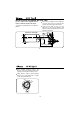
ENGINE EXPLODED VIEW 14 14-1 N.+M3.5x5 13 12 C.M2.6x8.6 15 9 11 8 25 C.M2.6x7 10-1 10-2 C.M3x25 10 7 22 3-1 C.M2.6x5 4 24 17 6 18 C.M3x8 23 5 21 19 1 2 25-1 20 3 Type of screw C...Cap Screw M...Oval Fillister-Head Screw F...Flat Head Screw N...Round Head Screw S...
ENGINEN PARTS LIST 31 No. Code No.
CARBURETOR EXPLODED VIEW 4 5 S.M3x3 1 2 6 N.+M3.5x5 3 9 7-7 8 7-5 7-4 7-6 7-2 7 S.M3x3 7-3 Type of screw C...Cap Screw M...Oval Fillister-Head Screw F...Flat Head Screw N...Round Head Screw S...Set Screw 32 CARBURETOR PARTS LIST No. Code No.
O.S. GENUINE PARTS & ACCESSORIES SPINNER NUT 1/4"-28(L) SILENCER EXTENSION ADAPTORS SET LONG PROPELLER NUT SETS (23024009) (41651300) (73101000) Adaptor L12 Adaptor L20 M3.5x6 (4pcs.) CAP SCREW SETS (10pcs./sets) M3x8 M2.6x5 SUPER FILTER (L) (72403050) SPRING WASHER (20pcs.) 3.5(Black) (71521000) (79872035) (79871110) (79871010) LONG SOCKET WRENCH WITH PLUG GRIP M2.6x7 (79871020) The specifications are subject to alteration for improvement without notice.
36 URL : http://www.os-engines.co.jp 6-15 3-Chome Imagawa Higashisumiyoshi-ku Osaka 546-0003, Japan TEL. (06) 6702-0225 FAX. (06) 6704-2722 C Copyright 2006 by O.S.Engines Mfg. Co., Ltd. All rights reserved. Printed in Japan.