3500 Series Tripod Kit You’re on steady ground ® 1
INTRODUCTION Thank you for choosing Oben! This versatile and durable Oben tripod and ballhead is a compact and lightweight kit that sets up quickly, folds up neatly into its own carry bag, and offers a variety of options ideal for the photographer on the go. The Oben AT/CT-3500 Series 5-section tripod features twist locks for fast and effortless height adjustment. Each leg can be positioned independently at three locking angles to ensure stable support when shooting on uneven terrain.
TABLE OF CONTENTS Key Features______________________________________ 4-7 Ballhead Operation_______________________________ 8-14 The Tripod Mounting Screw_______________________ 8 Mounting the Ballhead____________________________ 9 Main Locking Knob Operation______________________11 Mounting the Quick-Release Plate to the Camera___ 9 Mounting the Camera and Quick-Release Plate to the Ballhead___ 10 Tension Knob (BZ-217T & BZ-226T only)___________ 12 Adjusting the Friction (BZ-217T & BZ-226T only)____ 13 Pan
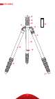
KEY FEATURES A E D C F G H B J I K L 4
KEY FEATURES A B Baseplate with Dual 3/8 -16 and 1/4-20 head mounting screw Two-piece center column (AT/CT-3535) One-piece center column (AT/CT-3565 and AT/CT-3586) C Low-angle center column D Center-column locking collar E Center-column twist lock (AT/CT-3535) F Strap mount G Leg angle adjustment lock H Integrated monopod I Retractable and removable weight hook J 180° folding legs K Leg adjustment twist locks L Integrated spiked feet Also Included: Carry bag Carry bag str
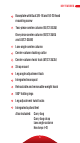
KEY FEATURES BE Series C A B I D E F H A C B BZ Series G D F E H 6
KEY FEATURES A Quick-release plate B Bubble level C 1/4-20 mounting screw D Quick-release knob E Pan knob F Main locking knob G Tension knob (BZ-217T & BZ-226T) H Panoramic base with 360° markings I 90° groove 7
OPERATION Ballhead Operation The AT/CT-3500 Series tripod and BE/BZ Series ballhead come assembled. During normal operation, the ballhead will occasionally have to be removed in order to make adjustments to the tripod. THE TRIPOD MOUNTING SCREW The tripod includes a mounting screw with a 3/8-16 thread on one end and a 1/4-20 thread on the other, allowing you to mount a tripod head with either size mounting socket. To switch between the two mounting screw sizes, do the following: 1.
OPERATION MOUNTING THE BALLHEAD When returning the ballhead to the tripod, follow these steps: 1. Tighten all of the knobs on the head. 2. Align the ballhead socket with the tripod mounting screw. 3. Rotate the ballhead clockwise onto the tripod, and tighten it by hand. To prevent damage to the ballhead and mounting screw, do not overtighten. Note: If a different size mounting screw is needed to mount the ballhead, refer to The Tripod Mounting Screw section above for instructions.
OPERATION Ballhead Operation (continued) Note: If a 3/8-inch mounting screw is needed, use the included 1/4 to 3/8 adapter bushing. Warning: Some manufacturers’ plates do not meet our specifications and may not lock your equipment securely in the Oben quick-release clamp. Please test all camera and lens plates made by manufacturers other than Oben to ensure compatibility.
OPERATION Warning: Always use one hand to secure the camera while adjusting the ballhead, and make sure that the lock is engaged before letting go of the camera. MAIN LOCKING KNOB OPERATION The main locking knob locks and unlocks the ballhead, which allows for changing the position of the camera. When changing camera positions via the main locking knob, always keep one hand on the camera. Turn the knob counterclockwise to unlock the head, and clockwise to lock it.
OPERATION Ballhead Operation (continued) TENSION KNOB (BZ-217T & BZ-226T BALLHEADS) The tension knob is used to control the amount of friction on the ball in order to maintain strict control when positioning it. The tension knob is the medium-sized knob, and it has a different look and texture than the main and panning locking knobs so you won’t confuse the two, even if you’re operating them by touch.
OPERATION ADJUSTING THE FRICTION (BZ-217T & BZ-226T BALLHEADS) To adjust the friction accurately, follow these steps: 1. Turn the locking knob and the tension knob clockwise until they are completely tightened. Then mount the camera and lens combination that you will regularly use. 2. Once the camera is securely mounted, hold the camera with one hand and completely loosen the locking knob by turning it counterclockwise until it stops.
OPERATION Ballhead Operation (continued) PANORAMIC BASE The base of the ballhead can be independently rotated 360°. The base is controlled by loosening the pan knob. 1. Twist the knob counterclockwise to unlock the base. 2. Rotate the base to the desired position, and then lock the base by turning the knob clockwise. Note: Degree markings on the base of the ballhead can be used to accurately set up panoramic shots.
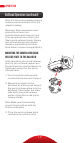
OPERATION LEG ANGLE ADJUSTMENT For stable support when shooting on uneven terrain, each leg can be adjusted to a preset angle. To set the leg angle, do the following: 1. Press and hold the leg angle adjustment lock. 2. Set the angle of the leg to one of the three preset positions. 3. Release the lock to secure the leg at the desired angle. CENTER-COLUMN ADJUSTMENT The center column can be used to adjust the height of the camera.
OPERATION Tripod Operation (continued) AT/CT-3535 1. If more height is needed, turn the center-column twist lock counterclockwise, and extend the upper center column to the desired height. 2. Turn the twist lock clockwise to secure the column. Note: Make sure the column is secure, but do not overtighten to avoid damaging the tripod. LOW-ANGLE SETUP The following instructions describe three ways to adjust the tripod for low-angle shots. Using the Center Column 1.
OPERATION Using the Low-Angle Center Column 1. Remove the ballhead from the tripod. 2. Loosen the set screw, and unscrew the baseplate from the center column. 3. Unscrew the weight hook from the bottom of the center column. 4. Loosen the locking collar, and slide the center column off of the tripod. 5. Insert the low-angle center column into the hole and tighten the locking collar. For extra stability, screw the weight hook into the bottom of the center column. 6. Set the legs to their lowest position. 7.
OPERATION Tripod Operation (continued) Reversing the Center Column Reversing the center column allows for mounting the camera upside down in order to get close to the ground or surface. To reverse the center column, do the following: 1. Unscrew the weight hook from the bottom of the center column. 2. Loosen the locking collar and remove the center column from the tripod. 3. Slide the center column into the tripod from underneath so that the ballhead is facing down toward the ground. 4.
OPERATION COUNTERWEIGHT When shooting in windy conditions or when using a telephoto lens, the stability of your camera is critical. A built-in spring-loaded hook at the bottom of the center column allows you to hang a counterweight, such as a sandbag (not included) or loaded equipment bag (not included), to provide increased stability.
OPERATION Tripod Operation (continued) SPIKED FEET The rubber non-skid feet are for use indoors or on flat surfaces. Spikes are for soft ground, grass, sand, and uneven terrain. To expose the spikes, follow these steps: AT/CT-3535: Remove the rubber feet by pulling them off. When finished using the spikes, replace the rubber feet. AT/CT-3565 and AT/CT-3586: Turn the retractable rubber feet clockwise.
OPERATION 3. Loosen the locking collar, and slide the center column out of the tripod. 4. Screw the end of the center column that housed the weight hook onto the end of the monopod leg. Note: As an alternative to using the ballhead, the camera can be mounted directly to the baseplate. (See instructions on switching the mounting screw size in The Tripod Mounting Screw section on page 8.) FOLDING LEGS For the most compact storage and transport of your tripod, the legs can be folded up 180°. 1.
SPECIFICATIONS AT/CT-3535 AT/CT-3565 AT/CT-3586 Maximum Height 51 in. with Center (129 cm) Column Extended 61.8 in. (157 cm) 62.5 in. (158.7 cm) Maximum Height 41 in. w/o Center (104 cm) Column Extended 53.3 in. (135.4 cm) 54 in. (137.1 cm) Minimum Height 8.2 in. (21 cm) 9.1 in. (23.2 cm) 8.5 in. (21.5 cm) Folded Length 12.3 in. (31.3 cm) 16.1 in. (40.9 cm) 16.6 in. (42.3 cm) Maximum Load 9 lb. (4.1 kg) 20 lb. (9.1 kg) 27 lb. (12.24 kg) Weight 2.85 lb. 2.5 lb. (1.29 kg) (1.13 kg) 3.
WARNINGS ! Warnings: • Do not exceed the tripod’s maximum load capacity (see tag on tripod). • Ensure that all appropriate locks are engaged when necessary. • Tripod should be used only in temperatures between -22° and 140° Fahrenheit. • Do not operate in salt water. Dry tripod off if it becomes wet. • Remove the camera from the tripod during transport. • Keep out of reach of children.
www.obensupports.com 24 GG2 Oben is a registered trademark of the Gradus Group. © 2018 Gradus Group LLC. All Rights Reserved.