
User guide

Installation Instructions
Model Number 1051-00
(877) 867-2312 • www.oberonwireless.com
Rev. 2 06/05/14 Oberon, Inc. •
••
• 1315 South Allen Street •
••
• State College, PA 16801 Copyright 2013
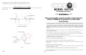
Figure 4 - Wall installation.
Assembly Components:
- Ceiling enclosure Model 1051-00 assembly – 1 each
- Decorative screw covers – 4 each
- Mounting hole legend – 1 each
- Keys for access door lock – 2 each
- Firestop Grommet – 1 each
- 1" Conduit Connector – 1 each
- Hanger wire – 4 each
If any of these items are missing,
contact your Oberon representative.
Find a flat work surface to assemble
the ceiling enclosure, access point
and antenna(s) prior to mounting in
ceiling.
Step 1 –
Remove the metal hole
cover(s) and install clamp
connector(s). Use two clamp
connectors if both power and data
lines are to be installed. If only a data
line is required (when using power
over Ethernet), only one clamp
connector will be required (Reference
Figure 1).
Step 2
–
(Any manufacturer’s access points) Install the access
point’s mounting plate to the enclosure’s “T-Bar” bracket using the
manufacturer’s instructions for attaching the mounting bracket to a
ceiling tile grid (T-Bar). Attach the Access Point to the mounting
plate. (Ref. Figure 2b) Proceed to Step 3
Step 3 – If applicable, install the antenna(s) per the instructions
included with optional antenna kit. After installation, connect the RF
coax cable from the antenna to the access point.
The assembled unit is now ready for wall or ceiling installation.
Page 2
Step 4 – To prepare the wall/ceiling for installation, cut a
14" X 14" square hole in the gypsum board (Reference
Figure 3). The hole should be located centrally between
two adjacent studs/joists. There must be a minimum of
4" of free space available behind the wall to allow for
clearance of the enclosure.
Note: Take proper safety precautions as many
wall/ceiling areas may have electrical or plumbing
located behind them.
WALL MOUNTING:
Step 5 – To install the enclosure in the wall, bring the data
and, if required power lines into the enclosure through the
cable clamps.
Position the enclosure so that the mounting holes are centrally
located with the studs (16" centers, Reference Figure 4).
For metal studs, use #10 sheet metal screws (or, for wood
studs, use #10 wood screws). The screws should be a
minimum of 1" in length.
Securely tighten the screws, being sure that the screw is
inserted directly into the stud*.
*NOTE: Alternatively, if no studs are available for mounting, drywall anchors may be used.
CEILING MOUNTING:
Step 6 – Run the data and power cable (if required) through the conduit connectors located on sides of the access point
enclosure. In order to maintain a separation of signal and power, install the data and power cables through opposite sides of
the enclosure utilizing the two knock-outs provided. Pull the data cable through the conduit connector far enough to allow
attachment to the access point (8" - 10"). Snap the grommet on to the cable and slide it inside the conduit connector.
Position the enclosure so that the mounting holes are centrally located with the joists (Reference Figure 5).
For metal joists, use #10 sheet metal screws (or, for wood joists, use #10 wood screws). The screws should be a minimum of
2" in length.
Page 3
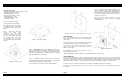
Figure 1 - Cable clamp installation.
Figure 2 - Install access point.
Figure 3 - Prepare wall or ceiling by cutting 14" X 14" opening.