
Owners Manual

20
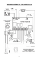
REPLACEMENT PARTS PROCEDURE
IT IS RECOMMENDED THAT ALL OCEANAIRE UNITS
BE SERVICED BY A QUALFIED AIR CONDITIONING SERVICE TECHNICIAN
WARNING—TO AVOID INJURY, DISCONNECT UNIT POWER
PRIOR TO SERVICING
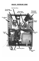
A. FAN MOTORS
1. Remove cabinet's left-side panel (when looking at the front of the unit).
2. Evaporator fan motor—disconnect evaporator motor wires from evaporator fan
contactor and power module. Condenser fan motor—disconnect condenser
motor wires from condenser fan contactor.
3. For all model sizes 12, 18, 24, and 36, remove the screws securing motors and inlet-
ring to blower housings (all screws are external and visible), and remove blower
wheel-motor assembly. Remove the blower wheel set screw and disassemble the blower
wheel from the motor shaft and remove the motor.
For model size 60—loosen blower wheel shaft set screw, and remove the screws
securing the motor mount to the blower housing and remove motor and mount. Remove
the motor from the motor mount.
4. Install the new motor, reversing the removal procedure.
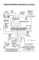
B. ELECTRONIC CONTROLLER (THERMOSTAT)
To remove the heat/cool display, remove the cabinet's left-side panel (from front).
Locate the two nuts securing the display to the front panel. Unplug the display cable
and remove display. Install new display and secure. Plug in display cable.
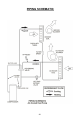
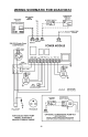
C. POWER MODULE
To remove the power module, remove the rear control box cover. Disconnect wires
(one at a time), and re-attach each wire, while holding replacement module in other hand.
Once all wires have been reconnected in accordance with the wiring diagram, install new
power module.
D. CONDENSATE PUMP (ON ALL 5-TON UNITS, OR ON UNITS WHERE
THE CONDENSATE PUMP KIT HAS BEEN INSTALLED)
1. Remove side panel.
2. Remove brackets securing condensate pump in base pan, or condensate tank tray pan
3. Disconnect pump wire leads at Molex connectors. Remove retainer clamp and tubing.
4. Replace pump, install by reversing procedure.
E. HIGH PRESSURE SAFETY SWITCH
1. Remove cabinets right side panel, or right rear side panel of Model 60.
2. Remove flare nut that secures capillary to the refrigeration system high pressure side.
A schrader valve is located in the discharge port which allows removal without losing
the refrigerant charge.
3. Remove two screws that secure high pressure switch.
4. Disconnect wire leads from compressor contactor and condensate pump safety switch.
5. Install new High Pressure Control, reversing the procedure.
To gain access to compressor and compressor run capacitor, remove left hand side
panel.