Micro Air Corporation FX-Maxx THERMOSTAT Operations Manual B MODE I>'n] AUTO I>'>" COOL IMMM'IHEAT - ISPEED FAN ] [POWE1 MOISTURE CONTROL Eil II_I I' c na MANUAL AUTO Sit~T :: 1,,1 OCEANAIRE, INC. 6216 Oakton Street Morton Grove, IL 60053 ::'RGE SETPOINT [Tn..] PHONE: 847-583-0311 FAX: 847-583-0312 E-MAIL:OCEANAIRE6@aol.com WEB: www.oceanaire-inc.
FX-Maxx Operations Manual CONTENTS FX-Maxx Operations Manual Micro Air Corporation 124 Route 526 Allentown, NJ 08501 BASICOPERATION. ...... ... ...... ... OPERATOR CONTROLS AND DISPLAY PANEL 2&3 ... MODES OF OPERATION MOISTURE CONTROL MODE. 1 4 ... 4 FANMODES 5 SPECIFICATIONS 6 WIRING DIAGRAMS ...... .... . . ......... ..
BASIC OPERATION FX-Maxx Operations Manual POWER BUTTON Press the power button once to toggle the unit to the on mode. Press the power button again to toggle the unit to the off mode. FAN BUTTON Press and release the fan button to advance from auto to manual fan. INb':lI] AUTO Press and release to increase the manual fan MODE ""'"Mi. COOL speeds, 1 through 6. Press and release again I':':II'IIIIHEAT returns to the auto fan mode.
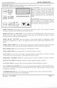
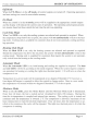
OPERATOR CONTROLS AND DISPLAY PANEL FX-Maxx Operations Manual Refer to figure 1 for the buttons locations and display functions listed on the following pages. FX-MaxxDisplay Panel 10 9 5 - 8 [::Jt:;i ~ I;:;'" 7 AUTO ~~~ 18 MOISTURE CONTROL II' 2 [ SPEED FAN ] .. tm;"? 13 14 MANUAL 12 AUTO 15 1 6 8 IIImoo TEMP ELECT INSIDE DISCHARGE I, I SETPOINT ~~ 16 17 4 3 Figure 1: FX-Maxx Control Buttons and Indicator Displays 1.
FX-Maxx Operations Manual 5. MODE BUTTON The mode button is used to select one of the four operating modes. Press and release the mode button and the FX-Maxx will advance to the next mode. Continue to press and release the Mode button until the desired operating mode is reached. The mode selected is indicated by the Mode LED, i.e., Cool, Heat, Automatic or Moisture Mode. " 6.
FX-Maxx Operations Manual MODES OF OPERATION Off Mode When the FX-Maxx is in the off mode, all control outputs are turned off. Operating parameters and user settings are saved in nonvolatile memory. On Mode When the control is in the on mode, power will be supplied to the appropriate control outputs and the display will indicate the current state of operation. The operating and program parameters resume based on those stored the last time the unit was operating.
FAN MODES FX-Maxx Operations Manual Automatic Fan Speeds FX-Maxx has 6 automatic fan speeds. Speed 6 is high, 3 is medium and 1 is low or the slowest speed, Automatic fan mode allows the FX-Maxx to determine the required fan speed based on room temperature. The closer the room temperature is to the set point, the slower the fan will run. This permits a balance between the most efficient temperature control and slower, quieter fan speeds.
SPECIFICATIONS FX-Maxx Operations Manual SPECIFICATIONS SET POINT RANGE 55°F to 85°F TEMPERATURE RANGE DISPLAYED OaF to 150°F TEMPERATURE SENSOR RANGE... . " ... ... ... .. . .. . ... OaF to 150°F FREQUENCY 50 OR 60 Hz """ FAN OUTPUT... ... """ ... '" ...
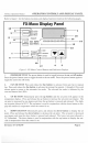
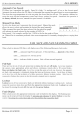
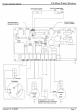
FX-Moxx FX-MAxx f!l.erations Manual WIRING DIAGRAM Tank Full Cutout Switch C Place this sensor in discharge air stream ..J::.. 1 n n~ DISPLAY ~ OAT/H20 / I I r-- Sdr ODD 00 g qg 01 I c::> g ..J::.. 0 :R:: ~ ~ =~ = qOonD qI Place this sensor in returnairstream ~I\I 11\1 C:::::>I OB olNO ~ ICLo =>- QClo1o~IO\'-'{Jq~ DI ID DD On Jpl i ~ 0 t AC -1 L1 L2 Compressor Reversing VOlve 11OVor 230V or trOlsformer con be comected between valve output Revision: 03 01/02/98
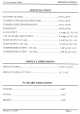
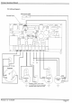
FX-Maxx f!J!.erationsManual FX1-WilingDiagram High Pressure Switch \ nn D-~.So-t DISPLAY OATIH2O OB 00 q ~ I °n ~ 0 n 1:11... J.W I 'io ~ 0a 0 9dr. ~-C::::::>I o 0 QDjJ 01 c:::JQOO~ 0g QI"IHP ~ ~ d~n~nnONW D V~~g CJ! On nOc=> -t 7'= I dB: D -c::::J- 1° B 0 L1 L2 Compressor Reversing valve 11OV or 230V or transformer can be connected between \/ClIve output anv valve.