
User Manual

A8906 rev B
OptiMizer 4
Users Manual
For SuperFlex 4 Systems
Optimizer
The OPT4 Optimizer is a hand held user
interface with a keypad and an alphanumeric
display. It is used as a calibration and diagnostic
tool, to display various system values, and to
make adjustments to the SB family of controllers.
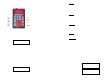
When a joystick is operate d, the Optimizer
display will change to this. The upper right
portion identifies the active channel or function,
and the lower right portion indicates the actual
output value. In this example, function 1
direction B (Fn1B) is active, with an output PWM
duty cycle of 72.5%. This channel has been
customized to read “Rotate Left”. As the joystick
is moved, the displayed value will change. If
more than one joystick is operated at the same
time, so that several outputs are active, the
Optimizer display will show the channel who’s
joystick was most recently moved.
There are five adjustment select keys - Threshold,
Maxout, Low Range, Ramp Up and Ramp Down.
These keys are used to select one of these 5
parameters to adjust.The Direction Select key toggl es
(alternates between) the A and B direction. This key
only functions when all joystick controllers are off. The
Optimizer automatically selects the direction when a
joystick is operated; this makes active adjustments easy
to perform.
The Function Select chooses on e of the 4 channels for
adjusting. This key only operates when all controlle rs
are off. Each time this key is pressed, the next function
(or channel) is selected, that is 1 ... 2 ... 3 ... 4 ... 1 ...
etc. The Optimizer automatically selects the function
(channel) whenever a joystick is operated, making
active adjustments easy to perform.
The Menu key accesses less frequently used items,
other information and diagnostics. A “three key menu”
system allows additional functions and features to be
easily added to SF4 while still having a universal
Optimizer. The Enter key is used to step through the
various menu items. The section “Diagnostic Menus”
below describes the Menu and Enter key functions.
The Plus and Minus keys are used for changing the
various adjustments (threshold, ramp, etc.). The
process is described below. The Run key must be
pressed after making an adjustment so the new value is
saved.
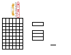
Figure 14 identifies various items that are displayed
when you are making an adjustme nt. The “value” is
flashing (blinking on and off) and will cha nge as the
Plus or Minus keys are pressed. The Channel
(Function) and Direction a re displayed generically on
the bottom line, and as the actual machine’s function s
on the top line. The parameter being adjusted (in this
example threshold) is shown at the upper left.
CAUTION - Be sure to press the RUN key after making
an adjustment or the new setting will be lost
Adjustments
Threshold
is the amount of output that causes the
machine to just start to move or operate. The
Threshold value represe nts a PWM percent duty
cycle, which corresponds to the initial voltage
signal driving the valve when the Joystick handle
is moved slightly from its off position.
Max Out
or maximum output is the amount of
output that causes the machine to operat e at
maximum desired speed. The Max Out value
also represents a percent duty cycle,
corresponding to the voltage signal driving the
valve when the Joystick handle is fully deflected
(and high range is selected).
Low Range
sets the limited amount of output
signal when the Joystick handle is fully deflected.
The Low ange setting represents a percentage of
the Maximum Output value.
Threshold, Max Out and Low Range adjustments
are made in 0.5 % steps.
Ramp Up
sets the time the machine’s function will
take to increase (accelerate) from off to full on.
This adjustment is made in tenths of a second.
Ramp Down
sets the time required for the
machine’s function to decrease (decelerate) from
full on to off. Ramp Down adjustments are also in
tenths of a second.
Diagnostic Menus
Various pieces of information are available in the
Diagnostic Menu mode. This mode is started by
pressing the “Menu” key. The Optimizer displays
the first menu item. Press the Enter key to step
through all of the menu items. The first four menu
items display fixed data. Two examples are
shown at the right.
The valve PWM frequency for the first two outputs
(channels 1 and 2) is followed by the valve
frequency for the second two outputs (channels 3
and 4). Next the OEM part number and serial
number are shown.
RUN MODE, NORMAL
FUNCTIONS OFF
RUN: ROTATE L
Fn1B 72.5%
FREQUENCY 1 2
100HZ
OEM PART NUMBER
SF4-4-200.00X
FRONT