IMPORTANT-READ THIS BEFORE RUNNING 1.Before Starting •Please read manual carefulyl (With a parent, guardian or a responsible adult if necessary). 2.While Operating •Any running area you choose must be dry. Do not run vehicle near any water or wet areas. •Do not run on public streets. It is very easy to have the car run over or damaged by hitting obstacles or other surfaces. •Do not operate the car in tight confined places. The vehicle is very fast and will easily hit something.
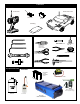
OVERVIEW Components Radio Control Car Transmitter Receiver Servo Parts Bag Included Items TOOLS NOT INCLUDED IN THE KIT Screw Cement 1.5mm Allen Wrench 2mm Allen Wrench CA Screw Cement 10289 - THREAD LOCK Instant Cemment 10239 - CA Body Reamer 10803 - BLACK 10804 - BLUE 10805 - PURPLE GEAR GREASE 2.
HNT-3 2.4GHz RADIO SYSTEM OVERVIEW HNT-3 Transmitter 1.Transmitter Antenna *Carefully read the instruction manual of your radio controller before using and keep it in a safe place as a reference introduction in the future. 2.Servo Reverse Switches 3.TX RF Module And Binding Button 4.Power LED 5.Power Switch 1 6.Steering Dual Rate Trim LED 7.External Charging Jack 10 12 8.Fail Safe Button 14 9.Throttle End Point Adjustment Knob 2 10.Steering End Point Adjustment Knob 3 4 11.
CAUTION • To use your Radio with your models correctly and safely, read this manual carefully and keep it in a safe place for future reference. Warning: 1. This product is only equipped for radio controlled cars; 2. The usage of this product should be approved by local law or regulations; 3. We will not be responsible for the damages caused by unauthorized modification, adjustment or replacement of parts on this product; 4. The manual may be change without prior notice.
AUX Channel Function (CH3) •This switch control the transmitter’s third channel. A servo plugged in this Channel 3 will move to full travel in one direction when the switch is in the “AUX” position, then move the switch to the “OFF” position the servo will move in the opposite position . This channel can be use to turn on all sort of things in your vehicle. For example, lights, on board camera etc..... l Steering Dual Rates Setup INC ST.DR DEC ST.D/R SW •DEFINITION: Steering Dual Rate (ST.
CHECKING YOUR DUAL RATE •To Check Your Dual Rate: 1. Turn your radio “ON” then turn “ON” your vehicle. 2. Check your steering on your radio by turning left and right several times. 3. Now turn your steering wheel all the way to the left or right whichever you choose and hold it while pushing the “DEC” button ( see fig. 1) on the “ST-DR” and hold it down, you should see that the wheel on your vehicle decrease in radius (see fig.
Steering Trim Please turn on your transmitter, plug in your battery and turn on your esc while making the adjustment of these settings. 1.Connect the receivers, servos, and other components and then turn on the power switches of the transmitter and receiver. 2.Be sure the steering trim and throttle trim on the transmitter are at their neutral position. 3.
Throttle Trim •Throttle neutral adjustments can be made by moving the throttle trim to the left or the right. •Racers Tip When using a electronic speed control, please set the throttle trim to neutral and make adjustments to the speed control. On a gas powered model, set the trim to the point where carburetor is fully closed in accordance with the engine instruction manual.
Handling Procedure For Batteries NOTICE THE DIRECTION OF BATTERY COVER •Battery Replacement 1) Remove the battery cover from the transmitter by sliding it in the direction of the arrow. 2) Remove the used batteries. 3) Load the new 8 AA size alkaline, or Nickel Metal Hydride (NimH) rechargeable batteries, and pay very close attention to the polarity marking on the batteries. 4) Slide the battery cover back onto the case.
PLASTIC PARTS FOR USE 40921 BUMPER & RADIO TRAY POST & BODY POST 37100 SHOCK ABSORBER 40836 FRONT & REAR LOWER ARM 40839 FRONT C HUB 40835 DIFF.
PLASTIC PARTS FOR USE 40943 FRONT BUMPER 40944 REAR BUMPER 37381 BALL END (4mm) 40945 REAR BUMPER BRACE 40541 RECEIVER BOX
PLASTIC PARTS FOR USE 40947 BODY POST & CENTER BRACE 40841 FRONT KNUCKLEARM 40834 SERVO SAVER 40802 STEEL SPUR GEAR (46T) 40844 CENTER DIFF.
1 ASSEMBLY OF THE FRONT AND REAR DIFF. *Build two differentials for front and rear. Step 2 Step 1 4x4 mm 30780 2x12.8mm Pin Oil .....x4 Oil 94034 4x4mm Set Screw 30780 .....x2 40808 40808 40009 P6 O-Ring 30780 37450 .....x4 37450 40803 40009 40835 40009 37450 10x15mm Ball Bearing 40805 .....x4 40805 2 ASSEMBLY OF THE FRONT AND REAR DIFF. Build two differentials for front and rear. Tighten Step 1 Step 2 2.6x10mm 30776 40805 30776 4x10mm Washer 30773 Tighten the diff screws in this order.
4 ASSEMBLY OF THE CENTER DIFF. 2.6x10mm Tighten Step 1 Step 2 30776 40805 30773 Tighten the diff screws in this order. 30776 4x10mm Washer 94046 2.6x10mm Flat Head Screw 30773 4mm Cross Pin .....x8 1 3 4 2 40011 .....x4 •Apply silicone oil to the differential gear during assembly. CENTER 10233 - 5000WT .....x2 5 ASSEMBLY OF THE FRONT GEAR CASE Step 1 94034 4x4mm Set Screw Step 2 .....x1 w t re en Sc em C 4x4mm 40840 40806 37430 5x11mm Ball Bearing .....
7 ASSEMBLY OF THE FRONT LOWER ARMS •A 3x8mm set screw is used to adjust ride-height. 94035 3x8mm Set Screw .....x2 94004 3x12mm Hex Screw .....x2 Ensure Free Movement 40836 3x8mm 40837 40825 3x53mm Arm Shaft .....x2 40825 Ensure Free Movement 40837 • Notice the direction of the front lower arm holder in rear. 40813 Up 40825 3x12mm 40836 8 ASSEMBLY OF THE FRONT UPPER ARMS •Approx. 8.5mm Step 1 Step 2 40838 40826 Ensure Free Movement 40837 30403 94004 3x12mm Hex Screw .....
10 ASSEMBLY OF THE FRONT SUSPENSION ARMS Assemble both right and left sides. •Insert drive shaft into cap joint before assembly. 94001 3x4mm Hex Screw .....x2 94005 3x16mm Hex Screw .....x2 Ensure Free Movement 3x4mm 40823 3x25.8mm Arm Shaft .....x2 40823 3x16mm 11 ASSEMBLY OF THE FRONT STABILIZER Assemble both right and left sides. •Makes two rods for left and right hand-side. 94035 3x8mm Set Screw 40848 .....x2 30341 30403 6mm Ball 3x8mm .....x2 30403 94005 3x16mm Hex Screw 3x16mm .....
13 ASSEMBLY OF THE SERVO SAVER 40810 Step 2 Step 1 Ensure Free Movement Step 3 40922 40834 40834 40834 37360 37360 Servo saver spring preload. 37220 •Approx. 0.5mm 37220 King Pin Bushing 37220 .....x2 3x8mm 37360 94002 3x8mm Hex Screw 40809 3x8mm Do Not Over Tighten .....x2 14 ASSEMBLY OF THE SERVO SAVER AND THE STEERING TIE-ROD Screw Cement 3x8mm 3x8mm Step 1 Screw Cement Ensure Free Movement Step 2 40834 3x8mm 3x8mm 40834 40834 94002 3x8mm Hex Screw Ensure Free Movement 37381 .
16 ASSEMBLY OF THE FRONT BODY POST Assemble both right and left sides. Step 1 Step 2 40947 2.6x15mm 40947 94004 3x12mm Hex Screw .....x4 40947 3x12mm 94005 3x16mm Hex Screw .....x2 94054 2.6x15mm Screw .....x2 40947 3x16mm 3x12mm 17 ASSEMBLY OF THE FRONT BODY STAY ONTO FRONT GEAR CASE 94041 3mm Nylon Nut .....x2 94005 3x16mm Hex Screw .....x2 3x16mm Tighten 18 ASSEMBLY OF THE FRONT BUMPER 3x18mm 94006 3x18mm Hex Screw .....
19 ASSEMBLY OF THE FRONT BUMPER 40943 94004 3x12mm Hex Screw 3x12mm .....x2 20 ASSEMBLY OF THE REAR GEAR CASE w t re en Sc em C 4x4mm Step 1 3x10mm Step 2 40921 40840 37430 5x11mm Ball Bearing 40806 .....x2 37430 38254 3x10mm 37430 38254 12x15x0.25mm Shim 94003 3x10mm Hex Screw 40804 .....x2 40840 .....x4 3x40mm 38254 40815 40945 94055 3x40mm Hex Screw .....x2 3x40mm 21 ASSEMBLY OF THE REAR SHOCK STAY 40870 3x10mm 3x10mm 94003 3x10mm Hex Screw .....
ASSEMBLY OF THE REAR CENTER BRACE 3x15mm 40947 40947 40947 94003 3x10mm Hex Screw .....x1 94005 3x16mm Hex Screw .....x1 3x10mm 23 ASSEMBLY OF THE REAR LOWER ARMS •A 3x8mm set screw is used to adjust ride-height. 94035 3x8mm Set Screw 94004 3x12mm Hex Screw 40825 3x53mm Arm Shaft .....x2 Ensure Free Movement 3x8mm 40836 3x8mm .....x2 40837 .....x2 40825 40837 40816 40836 Ensure Free Movement 3x12mm 24 ASSEMBLY OF THE REAR SUSPENSION ARMS Assemble both right and left sides.
25 ASSEMBLY OF THE REAR SUSPENSION ARMS Assemble both right and left sides. 3x12mm 37100 40828 (3x60mm) 30403 30403 6mm Ball 37100 .....x4 30403 94004 3x12mm Hex Screw .....x2 94005 3x16mm Hex Screw .....x2 •Approx. 47mm 3x16mm 26 ASSEMBLY OF THE REAR STABILIZER Assemble both right and left sides. *Makes two rods for left and right hand-side. 94035 3x8mm Set Screw .....x2 40848 30341 30403 6mm Ball 3x8mm .....x2 40848 30403 94005 3x16mm Hex Screw 3x15mm .....
28 ASSEMBLY OF THE REAR BODY POST Assemble both right and left sides. Step 1 Step 2 40947 2.6x15mm 40947 94004 3x12mm Hex Screw .....x4 40947 3x12mm 94005 3x16mm Hex Screw .....x2 40947 3x16mm 3x12mm 94054 2.6x15mm Screw .....x2 29 ASSEMBLY OF THE REAR BODY STAY ONTO REAR GEAR CASE Step 1 94041 3mm Nylon Nut .....x2 94020 3x12mm Flat Head Hex Screw .....x2 94004 3x12mm Hex Screw .....x2 94005 3x16mm Hex Screw .....
31 ASSEMBLY OF THE REAR BUMPER 40945 3x16mm 94005 3x16mm Hex Screw .....x2 32 ASSEMBLY OF THE REAR BUMPER Assemble both right and left sides. 3x18mm 94006 3x18mm Hex Hex Screw 40944 .....x2 33 ASSEMBLY OF THE REAR BUMPER 40944 3x10mm 94003 3x10mm Hex Hex Screw .....
34 ASSEMBLY OF THE CENTER DIFF. MOUNT 3x10mm Step 2 Step 1 Step 3 40844 40830 3x3mm 40844 30171 40844 40844 40830 •Approx. 12mm 94033 3x3mm Set Screw .....x1 94003 3x10mm Hex Screw .....x4 40844 35 ASSEMBLY OF THE BRAKE DISK INTO CENTER DIFF. 26 Step 2 Step 1 3x3mm 30171 3x12mm * Remove the double-side tape before assembly. 40044 38271 40044 38272 double-side tape 40042 • Leave a 1.5mm space between the two brake pads. 40044 94033 3x3mm Set Screw .....
37 ASSEMBLY OF THE FRONT GEAR CASE ONTO CHASSIS 3x10mm 94019 3x10mm .....x10 Flat Head Hex Screw 38 ASSEMBLY OF THE REAR GEAR CASE ONTO CHASSIS 94019 3x10mm Flat Head Hex Screw .....x4 94021 3x15mm Flat Head Hex Screw .....x4 40943 3x15mm 3x10mm 39 ASSEMBLY OF THE CENTER DIFF. ONTO CHASSIS 40942 (109mm) •Insert the drive shaft into the cap joint before screwing in center diff. onto chassis. 40942 (109mm) 3x10mm 94019 3x10mm Flat Head Hex Screw .....
40 ASSEMBLY OF THE FRONT STEERING SERVO STEERING SERVO 34026 3x8mm 34026 3x16mm 94040 3x8mm Washer 94005 3x16mm Hex Screw .....x4 .....x4 41 ASSEMBLY OF THE STEERING TIE-ROD Step 1 Step 2 30400 (3x46mm) 37381 37360 37381 40967 Approx. 31.9mm Use the screw provided with your servo . 42 ASSEMBLY OF THE STEERING ROD AND RADIO TRAY Step 2 Step 1 3x12mm 2x8mm 3x8mm 10282 40541 40541 SERVO Switch 94040 3x8mm Washer 2x8mm Screw .....
43 ASSEMBLY OF THE RADIO TRAY AND RECEIVER BOX 40541 Step 1 30560 Step 2 3x10mm 40642 37410 •Use the original battery case or rechargeable hump pack battery. •Connect battery wire to switch. 40541 Battery Case •Put the servo wire into receiver box and connect to receiver. Receiver 94003 3x10mm Hex Screw .....x2 44 ASSEMBLY OF THE RADIO TRAY ONTO CHASSIS •Snap into 4mm ball & socket. 3x10mm 94019 .....
46 ASSEMBLY OF THE CLUTCH Step 1 Step 2 •Only use the 10091 pilot shaft for threaded crank shaft engine. 10091 Pilot Shaft (Not Included) w t Scre en Ce m Threaded Crank Shaft 38430 40814 Scre w Cem ent 40814 10009 •Fit the flywheel using a pair of the plIer and cross wrench. 38430 •Place the clutch shoes with the clutch springs over the 3 pins of the flywheel. •Using a screw driver or needle nose pliers and bend the small end of the clutch spring behind the pilot shaft 10102 than press down.
49 ASSEMBLY OF THE MANIFOLD AND MUFFLER Step 2 94034 4x4mm Set Screw .....x1 94036 5x4mm Set Screw .....x1 40917 Step 1 95901 Zip tie 94018 3x5mm .....x1 Flat Head Hex Screw 10120 5x4mm 4x4mm 38397 40832 40970 40968 3x5mm 50 ASSEMBLY OF THE THROTTLE LINKAGE Step 2 Step 1 30800 2.5mm Nylon Nut 30172 94033 3x3mm Set Screw 3x3mm .....x4 30172 40967 10300 40060 2.5mm Nylon Nut 30801 2.6X18mm Screw .....x1 30800 30531 36140 30800 .....x1 2.6x18mm 3x10mm 94003 3x10mm Screw .....
52 ADJUSTING THE ENGINE CONTROL LINKAGES (Neutral) (Throttle High) (Brake) Approx. 0.5mm 10300 10300 Idling adjusting Screw Approx. 1mm gap Carburetor is Open fully •Turn on the Transmitter then Receiver and set the Engine Control Servo Trim to the neutral position. •Adjust the idling adjusting screw on the Carburetor to be open approx. 1mm gap. •Adjust both of the 10300 Engine Control and Brake linkage accordingly. •Adjust the Engine while it is not running.
55 ASSEMBLY OF THE FRONT SHOCKS CORRECT SHOCK ASSEMBLY *Assemble 2 sets for front. Step 1 Step 2 37100 2mm .....x4 37070 37100 37100 (NO.1) 30403 6mm Ball 94007 3x20mm Hex Screw 2mm 18mm 37070 P3 O-Ring •Carefully screw the shock shaft into the bottom of the plastic ball until the distance between the ball end and the shock body is 18mm for the front. •Note: Do not over tighten as the plastic ball will strip. 40845 .....x2 37100 40914 .....
57 ASSEMBLY OF THE FRONT SHOCK ABSORBER 3mm 94041 3mm Nylon Nut .....x2 3x18mm 94006 3x18mm Hex Screw .....x2 Assemble both right and left sides. 58 ASSEMBLY OF THE REAR SHOCK ABSORBER 3mm 94041 3mm Nylon Nut .....x2 94006 3x18mm Hex Screw .....x2 3x18mm Assemble both right and left sides. 59 ASSEMBLY OF THE TIRES AND WHEELS *Make four tires that are the same. Step 1 Step 3 Step 2 40952 •Use " Instant glue " and draw a line a round the rim where it attaches the tire .
60 ASSEMBLY OF THE WHEEL BEAD LOCKS •Assemble bead locks on all four tires. 2x6mm 40940 94057 2x6mm Screw .....x44 61 ASSEMBLY OF THE TIRE ONTO FRONT KNUCKLE AND REAR HUB ASSEMBLY OF THE FUEL TUBE 10177 10177 *A ssembled t ire and wheel. 40865 40865 4mm Nylon Nut .....
SETTING GUIDE FRONT CAMBER ANGLE SETTING REAR CAMBER ANGLE SETTING Positive Negative Positive Negative - - + + + - - + Turnbuckle Turnbuckle •Place the model car on flat surface. Raise the chassis to its maximum clearance before the wheels leave the ground. •Adjust the length of the front and rear upper arms so that the wheels are vertical to the ground. •Adjust the camber angle by turning the turnbuckle rod on the upper arms clockwise or counter-clockwise.
SCRT10 Set-Up Sheet Date:________________ Driver:_________________ Track:_______________/_______ Air Temp:_____80F_____ Surface Dsc. ______WATERED & DRY_______ Front Suspension Front Roll Center 1 Avg.
SCRT10 Set-Up Sheet Date:________________ Driver:_________________ Track:_______________/_______ Air Temp:_____80F_____ Surface Dsc. ______WATERED & DRY_______ Front Suspension Front Roll Center 1 Avg.
Warranty Period OFNA warranties that the Products purchased (the “Products”) will be free from defects in materials and workmanship at the date of purchase by the Purchaser. Limited Warranty (1) This warranty is limited to the original Purchaser (”Purchaser”) and is not transferable. REPAIR OR REPLACEMENT AS PROVIDED UNDER THIS WARRANTY IS THE EXCLUSIVE REMEDY OF THE PURCHASER. This warranty covers only those Products purchased from and authorized OFNA dealer.
TO: OFNA TECHNICAL SUPPORT 7 VANDERBILT, IRVINE, CA 92618 TODAY’S DATE: month________day______ 1. Print out form. 2. Fill out the form completely. 3. Make a copy of purchase receipt. All replacements/repairs will not be processed, unless accompanied by proof that item(s) was purchased. 4. Call OFNA technical support at (949)586-2910 for assistance. 1. Your name ____________________________ 2. Your address: ____________________________ ____________________________ 3.
OWNER’S REGISTRATION CARD OFNA Racing congratulates you on your purchase of our fine OFNA Product. With proper maintenance and handling this kit will provide many hours of enjoyment. The registration card should be filled out and mailed to OFNA Racing within 10 days of purchase date.