OFNA Racing 22692 Granite Way, Ste. B Laguna Hills, Ca. 92653 (949) 586-2910 Www.ofna.com RTR Instruction Manual PURE COMPETITION........... LIMITED EDITION OFNA/PICCO .
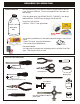
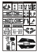
REQUIRED FOR OPERATION THINGS NEEDED You will need to buy a few items to start the engine and run the car. • Use 20% nitro CAR fuel. Do not use airplane fuels, they will over heat engine. • Buy long glow plugs, like OFNA/PICCO P-7 (#51007). Use plugs without idle bar. Do NOT buy hot plugs, like the MC-59. In your box you will find.. • #10218 - Red “C” size glow heater P-7S Glow Fuel 20% 51007 #10211 Battery Pack 1000 NiMh 5cell, flat............... $29.95 #10214 Battery Charger, Overnite $7.
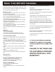
READ THIS BEFORE RUNNING Running a nitro kit is fun and easy, but to make this a safe and good experience you must observe a few rules. This kit is extremely fast, easily over 40MPH, and can seriously injure someone if you are not careful. Where to run car? • Any running area you choose must be dry. Do not run car near any water or wet dirt. • Do not run on public streets. It is very easy to have the car run over or damaged by hitting the curb. • Do not operate car in tight confined places.
* Align throttle servo same as shown. CHECKING ENGINE THROTTLE A C B 1. Insert AA batteries into transmitter (8 Pcs). 2.Turn on transmitter. 3.Turn on receiver. 4.Center throttle trims as shown . 1. Pull Full Throttle. 1. Push trigger to full brake position. 2. Adjust alum. Stopper to increase or decrease the brake. Brake © A Idle Position (A) Full Throttle (B) IMPORTANT CHECK RADIO THROTTLE AND STEERING SWITCHES BEFORE RUNNING CAR • Full throttle arm position.
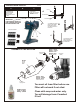
PLASTIC PARTS USED #30010 Main Gear Box #30751 - Frt & Rr Cases #30761 - Center Case (K type cases) #30769 Bevel Gear Set, for K type case.
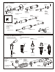
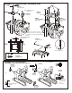
SHOCK ASSEMBLY 2.6mm Nut * Fit into groove. 2.6 x 5mm Washer Oil Seal 2mm Washer 1mm Washer Piston Shock Cylinder #32203 *Push Onto Shock Cylinder Option: Shock Shaft #32039 Dust Pusher (Yellow Rubber) #32237 O-Ring, rebuild 7mm E-Ring O-ring Pistons #32235 * Assembly 4 pieces of the shock Shaft . Teflon Piston Set #32291 * E-Ring must fit into groove as shown. Front, Short(w-gt) Shaft, 3.2mm #32051 * Short shaft for front.
ASSEMBLY OF NEW “K” STYLE DIFFERENTIAL CASE AND GEARS #31324 - FRONT OR REAR DIFF UNIT #31325 - CENTER DIFF UNIT 30769 Diff. Bevel Gear ( Large ) 30779 4 x 10mm Washer 30771 Diff. Shaft 30779 2 x 12.8mm Pin 30769 Diff. Bevel Gear ( Small ) 30769 Diff. Bevel Gear ( Small ) 30773 4mm Cross Pin 30779 4 x 10mm Washer 30779 P5 O-Ring ( Orange ) 30773 4mm Cross Pin 30779 0.5 x 26mm O-Ring * Position the O-ring as shown. 30769 Diff. Bevel Gear ( Small ) 30779 4 x 10mm Washer NB.
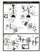
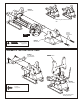
ASSEMBLY OF THE SPUR GEAR #31040 Steel Spur Gear #30111 * Notice the tapered holes are for the center diff. Only. 3 x 10mm Flat Head Screw & Nut M3 Nylon Nut #31323 Diff Unit, Center, Complete #30760 Diff Case, Center 3 x 10 mm Flat Head Screw #30111 3 x 10mm Flat Head Screw & Nut ASSEMBLY OF THE CENTER DIFF. MOUNT U.S. Revision has Quad Brakes #30620 #30170 7 x 19x 5mm Ballbearings Brake Joint #30201 #30620 Center Diff.
3 x 10mm Tapping Screw ASSEMBLY OF THE CENTER DIFF. AND BRAKE CAM Screw Cement 3 x 3mm Set Screw #30171 Brake Lever, Lower * Notice: The direction of the brake cam. #30213 #30652 Brake Cam Center Plate #30213 Brake Cam #30212 #30212 Bearing, Brake Cam 4X8mm Flanged Bearing, Brake Cam 4X8mm Flanged Parts drawn are not shown correctly. A few parts have been changed and may look different, but part numbers reflect the new parts. * Leave 3mm distance between brake cam and nut.
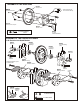
#30010 Main Gear Box * Make two gear boxes for front and rear. 4 x 20mm Flat Head Tapping Screw GEAR GREASE #30010 Main Gear Box 3 x 20mm Flat Head Tapping Screw ASSEMBLY OF THE FRONT SHOCK TOWER #36670 Alum. Blue Front Upper Arm Holder #36620 Front Shock Tower 4 x 10mm Tapping Screw #30340 Anti-roll Bar Kit 4 x 10mm Tapping Screw * Insert front stabilizer before assembly shock tower.
ASSEMBLY OF PIVOT BALL TYPE (M STYLE) SUSPENSION #36903 13.8mm Steering Ball x 4 #36904 14mm Alum. Nut x 4 #36905 Plastic Washer & Arm Adjusters #36901 Ball Type Knuckle Arm ( Right ) ( Left ) #36900 Front Upper Arm #36890 Front Lower Arm #36902 Rear Lower Arm ASSEMBLY OF THE FRONT SUSPENSION ARMS, M STYLE #36901 Assembly of the right and left hand side are the same. Ball Type Knuckle Arm ( Right and Left ) * Adjusr alum. Nut to keep steering ball smoot.
ASSEMBLY OF THE FRONT SUSPENSION ARMS, M STYLE Step 2 #36890 Front Lower Arm Assembly of the right and left hand side are the same. #36870 4x10mm Set Screw * A 4 x 10mm set screw is used to adjust the ride height. #36055 2.5 x 17mm Pin R * Approx 3mm. 5 x 5mm Set Screw #36054 Wheel Hub ( Alum. ) * Use 2.5mm Hex Wrench. #36900 Front Upper Arm R 5x5mm Set Screw 3mm * Do not over tighten 5x5mm set screw.
ASSEMBLY OF THE FRONT SUSPENSION ARMS, M STYLE Step 4 * Cut the sharded area as shown. Assembly of the right and left hand side are the same. 3mm E-Ring 3 x 3mm Set Screw #30102 Front Body Post 3 x 3mm Set Screw 3 mm E-Ring 3 x 8mm Tapping Screw 3x8mm Tapping Screw #30340 6mm Stabilizer Ball End #36640 Upper arm Shaft 1 0 R 3mm E-Ring Step 5 Assembly of the right and left hand side are the same.
ASSEMBLY OF THE FRONT SUSPENSION ARMS, K STYLE #36860 * Builds two front upper arms for left and right-side. . 5x40mm Turnbuckle #36690 Plastic, Arm Ball End 3 x 20mm Flat Head Tapping Screw #36020 Front, Upper Arms * If too tight, cut or sand to fit the shaded area as shown. 0.5MM #36850 7mm Ball 4 x 15mm Tapping Screw * Anticlockwise mark.
ASSEMBLY OF THE FRONT LOWER ARMS ONTO THE GEAR BOX, K STLYLE #36720 Assembly of the right and left hand side are the same. Lower Arms Stiffener (Alum.) 3mm E-Ring 4 x 10mm Tapping Screw 4 x 10mm Tapping Screw 1 0 * Insert drive shaft before assembly. #36630 Lower Arms Shaft R * Cut the sharded area as shown. #90021 3 x 3mm Set Screw #90021 3mm E-Ring 3mm E-Ring #30102 Front Body Post A-34B #30340 6mm Stabilizer Ball End 3x8mm Tapping Screw 3mm Nylon Nut 1 #36055 0 R 2.
ASSEMBLY OF THE STABILIZER ROD #30402 #30401 Assembly of the right and left hand side are the same. 6mm Plastic Stabilizer Ball End 3 X 30mm Tie Rod #30401 3 x 25mm Cap Screw #36610 6mm Plastic Stabilizer Ball End Spacer, Shock Support 3 x 15mm Screw * Insert into arms. #30411 6mm Ball Joint 1 0 R 14mm 3 x 25mm Cap Screw 10 20 30 40 50 3 x 15mm Screw mm Assembly of the right and left hand side are the same.
ASSEMBLY OF THE REAR SHOCK TOWER Assembly of the right and left hand side are the same. #36810 Rear Shock Tower 3 x 20mm Flat Head Screw #30340 Anti-roll Bar Kitr * Don't over tighten tapping screw, will cause bending. * Insert stabilizer before assembly of the shock stay. #36090 Rear Arm Holder & Toe-in ASSEMBLY OF THE REAR ARMS, K & M STYLE 4x16mm Flat Head Tapping Screw 3mm E-Ring #36720 #36630 Lower Arm Stiffener (Alum.) Arm Shaft Assembly of the right and left hand side are the same.
ASSEMBLY OF THE REAR HUB, K & M STYLE * Builds two upper Rods for left and right-side. #36880 5x60mm Turnbuckle #36690 #36053 Arm Ball End 8 x 16 x 5 Ball Bearings #36690 #36082 Arm Ball End Rear Wheel 8mm Axle Shaft #36053 8 x 16 x 5 Ball Bearings #36054 Rear Hub K or M Style #36850 7mm Ball #36055 2.5 x 17mm Pin * Anticlockwise mark. #36054 Wheel Hub ( Alum. ) 40mm 0 10 20 Assembly of the right and left hand side are the same.
3 x 25mm Cap Screw ASSEMBLY OF THE REAR UPPER ARM ROD Assembly of the right and left hand side are the same. G-01 Shock Support 3 x 25mm Cap Screw M3 Nylon Locknut 3 X 25mm Cap Screw M3 Nylon Locknut * Insert into rear hub.
ASSEMBLY OF THE REAR SHOCKS ONTO THE SHOCK TOWER Assembly of the right and left hand side are the same. #36610 Spacer, Shock Support #30411 6mm Ball Joint 3 x 8mm Washer rew t Scemen C 3mm Nylon Locknut * Insert shock ball end into arm.
ASSEMBLY OF THE WING STAY ONTO THE SHOCK TOWER 4 x 15mm Tapping Screw 3 X 25mm Cap Screw 4 x 15mm Tapping Screw M3 Nylon Locknut 3 x 25mm Cap Screw Wing Stay Assembly * Insert 3mm nylon locknut into win stay.
ASSEMBLY OF THE FRONT PLATE 0 10 20 30 40 50 mm #36700 * Made two steering rods for left and right-side. 3 X 10mm Screw Steering Ball End #36790 4 x 46mm Turnbuckle #36850 7mm Ball #36760 Front Plate #36850 7mm Ball #36700 * Anticlockwise mark. Steering Ball End 31mm * ASSEMBLY OF THE FRONT TORQUE ROD #36680 Steering Ball End #36680 7mm Ball & Socket Support #30380 #36790 4 x 46mm Turnbuckle Servo Saver Axle Posts * Anticlockwise mark.
ASSEMBLY OF THE FRONT PLATE ONTO THE FRONT GEAR BOX 3 x 10mm Tapping Screw 3 x 15mm Flat Head Screw 3 x 15mm Flat Head Screw Knuckle arm of the left-side. Scre w Cem ent Scre w Cem ent 1 0 R 3 x 10mm Tapping Screw 3 x 15mm Flat Head Screw ASSEMBLY OF THE FRONT GEAR BOX ONTO CHASSIS 1 0 R #36840 Chassis, Hard Coated * Insert the front bumper before assembly. #30240 Front Bumper 4 x 16mm Flat Head Tapping Screw 3 x 10 mm Flat Head Screw * A 3 x 10mm flat head screw are for servo post.
Center Diff. Assembly ASSEMBLY OF THE CENTER DIFF. ONTO CHASSIS #36110 Center Drive Shaft * Insert drive shaft into cap joint. 1 0 R 4 x 16mm Flat Head Tapping Screw 3 x 25mm Flat Head Tapping Screw #36110 Center Drive Shaft * Insert drive shaft into cap joint.
ASSEMBLY OF THE STONE GUARD 3 x 10mm Tapping Screw 3 x 10mm Tapping Screw #36820 Stone Guard #36820 Stone Guard 1 3 x 10mm Tapping Screw 0 R 3 x 10mm Tapping Screw 3 x 10mm Tapping Screw ASSEMBLY OF THE REAR TORQUE ROD #36710 Rear Stiffener & Body Mount #36700 Steering Ball End #36700 Steering Ball End #36710 Rear Stiffener & Body Mount #36790 4 x 46mm Turnbuckle #36850 7mm Ball 3 x 20mm Screw #36680 7mm Ball & Socket Support * Anticlockwise mark.
ASSEMBLY OF THE REAR BODY SUPPORTER ONTO REAR GEAR BOX 3 x 10mm Tapping Screw Rear Body Supporter Assembly 4 x 10mm Tapping Screw M3 Flange Nut 4 x 10mm Tapping Screw 3 x 10mm Tapping Screw M3 Flange Nut ( Steel ) 3 x 25mm Flat Head Screw 3 x 25mm Flat Head Screw
ASSEMBLY OF THE CLUTCH INTO ENGINE Notes: Non-Pull Start Engines... • Alum. Washer behind the flywheel is not needed when using Force engines or similar types. O.S. Engines will require washer spacer. 3 x 5mm Screw • To check!..place the brass corn #10330 (big hole) against the engine bearing, then flywheel. You should be covering one or two thread of the engine shaft. If this is the case, you do not need an additional washer behind the flywheel.
3 x 15mm Screw Pressure Nipple INSTALLATION OF THE FUEL TANK AND ENGINE ONTO CHASSIS #30280 Fuel Nipple Fuel Tank 3 x 15mm Screw Note Book Paper 3 X 20mm Cap Screw Plastic Post Plastic Post *Use note book paper to set gear backlash between spur gear and clutch bell gear. If the space is not correct the spur gear will be damaged. * Take the plastic post from the receiver box plastic parts.
ASSEMBLY OF THE FUEL TUBE * Connect to fuel tank pessure nipple. * Connect to carbulater. #10178 - Yellow #10179 - Lt. Blue Silicone Fuel Tubing, 3ft. * Connect to press nipple. * Connect to fuel nipple. ASSEMBLY OF THE RADIO TRAY AND SERVO 3 x 10mm Screw 3 x 10mm Tapping Screw 3 x 10mm Tapping Screw 3 x 10mm Screw Throttle Servo #36770 Steering Servo Radio Tray #30520 Radio Tray Post, Alum. * Take the radio tray post and servo post from receiver box plastic parts. In U.S.
ASSEMBLY OF THE RECIVER BOX 2x8mm Screw 2x8mm Screw 2x8mm Screw 2x8mm Screw 2x8mm Screw * Use the screw provided with your radio. #36780 Receiver & Battery Box #10280 Switch Cover Switch (with radio) ASSEMBLY OF THE RADIO TRAY ONTO RECEIVER BOX * Put the receiver and battery into box. Receiver Box Cover 3x10mm Tapping Screw * Use the horn & screw provided with your radio. 2mm Rod * Keep radio and battery from moving in box. Pack with foam.
ASSEMBLY OF THE RADIO TRAY ONTO CHASSIS 3 x 10 mm Flat Head Screw 3x10mm Tapping Screw #30560 3 x 10mm Tapping Screw Antenna Tube Use Alum. CNC posts for radio tray and not plastic type as shown! 3X10MM Flat Head Screw 3X10MM Flat Head Screw 3X10MM Flat Head Screw 3X10MM Flat Head Screw ASSEMBLY OF THE THROTTLE LINKAGE SYSTEM #30800 #30530 Throttle and Brake Linkage Parts (Plastic and all Hardware shown) 3X3mm Set Screw Plastic Throttle Ball Joint * Snap On.
ALIGN THROTTLE SERVO AND BRAKE SAME AS SHOWN ( Neutral Position ) Engine at idle ( Braking Position ) Brake is not on Brake is on Brake Adjust Nut ( Full Throttle Position ) Less Brake More Brake Loose Engine at full throttle Tighten * Tighten or loose the adjuster nut will change the brake.
ASSEMBLY OF THE FRONT STEERING ROD #30410 6mm Ball & Socket End #30402 #30410 3 X 30mm Tie Rod 6mm Ball & Socket End 3x12mm Screw #30410 6mm Ball & Socket End 3x12mm Screw #30410 6mm Ball & Socket End * To the steering servo saver. 20mm 0 10 20 30 40 50 mm 3 x 12mm Screw * Align the steering servo as shown.
ASSEMBLY OF THE TIRES, FOAM INSERTS AND WHEELS - Red White Lime Yellow #86091 Mini XX- Pin Tire R #86044 #86045 #86046 #86047 17mm 5-Star Wheels Front Knuckle Arm Assembly #15071 17mm Wheel Nuts Always use tire foam donut when building tires. IN ST GL ANT UE Foam T TAN INS LUE G * Apply instant glue into the groove of the wheel. Rear Hub Assembly #81091 - Med/soft #81092 - Med. WE RECOMMEND CA GLUE FOR RUBBER TIRES.
PAINTING TIPS For BUGGY STEP 1 Wash the inside of the body with detergent to remove any oil and dirt. Dry with lint free towel or a hair dryer. (Keep your hand clean.) STEP 2 Tools required are: Curved scissor , hobby knife and a quality masking tape. These can be purchase at your local hobby supplier. STEP 3 Use the curved scissors to trim the body to the guide lines provided on you body shell. STEP 4 Use masking tape on the inside of the body to mask out your design and windows prior to painting.
ENGINE BREAK-IN AND TUNNING (BREAK-IN THE ENGINE BEFORE DRIVING THE CAR!) • Choose a wide clear outdoor location with low dirt and dust. • Set the car on box or holder with wheels off the ground. • Turn on radio and car. Make sure throttle is at idle position. • Fill fuel tank and set master engine needle. • Prime fuel line and Heat glow plug before pull starting engine. • When started, let engine fast idle for two tanks of fuel.
0 1:1 SCREW SHEET 10 20 30 40 50 mm 3 x 5mm Cap Screw 3 x 3mm Set Screw 3 x 10mm Cap Screw 3 x 5mm Set Screw 3 x 8mm Set Screw M3 Nut M4 Nut 3 x 12mm Cap Screw 3 x 10mm Set Screw 3 x 15mm Cap Screw 3 x 20mm Cap Screw 3 X 25mm Cap Screw 3 x 5mm Tapping Screw M3 Nylon Locknut 3 x 15mm Set Screw M4 Nylon Kocknut 4 x 4mm Set Screw 4 x 10 mm Set Screw M3 Flange Nut ( Steel ) 5 x 5mm Set Screw 2 X 6mm Washer 3 x 8mm Tapping Screw 2 x 4mm Screw 2mm X 7mm Washer 3 x 10mm Tapping Screw 2 x 5mm S
#31296 Rear Pivot Ball Suspension System, Buggies ( Available For: 1/8 Scale Buggy-Ultra GT LX, Ultra MBX & MBX +, Worlds, Worlds ll ) ASSEMBLY OF THE REAR HUB Assembly of the right and left hand side are the same. 36082 Rear Wheel Axle Shaft * Take the 4mm set screw from your car kit. 36503 8x16mm Ball bearings 31304 Rear Hub 36870 4mm Set Screw * Make sure the pivot ball move smooth.
ASSEMBLY OF THE UPPER ROD INTO GEAR BOX Assembly of the right and left hand side are the same. 30061 4 x 25mm Flat Head Screw * Insert into rear hub. 3mm Nylon Lock Nut 4mm Nylon Lock Nut 3 x 25mm Cap Screw ASSEMBLE THE FRONT AND REAR GEAR BOX ONTO CHASSIS AS USUAL. SETTING GUIDE REAR WIDTH SETTING REAR CAMBER SETTING Adjust A and B to the same length. Adjusting B longer will make the rear tires toe-in (Positive). The rear camber adjustment can be make by changing the length of the upper rod.