
Instruction Manual
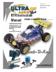
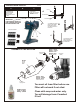
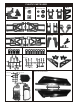
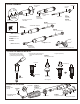
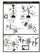
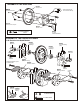
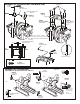
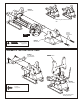
Table Of Contents

#32237
O-Ring, rebuild
Shock Cylinder
( Make 2 for rear. )
( Make 2 for front.)
OIL
2. Pull down piston, attach pressure top
and shock oil overflow with tissue
paper.
SHOCK ASSEMBLY
FILLING THE SHOCKS WITH OIL
ASSEMBLY OF THE SPRING
1. Pull down piston and pour oil into
shock cylinder. Remove air bubbles
by slowly moving piston up and down.
3. Tighten up shock cap.
*Pull down.
*Move Slowly.
*Leave 3mm.
*Push Onto Shock
Cylinder
Shock Shaft
Piston
* Be careful not to damage shock shaft.
Pressure Top
#32044
Shock Cap, Hard Coated
*
Fit into groove.
#32203
Dust Pusher
(Yellow Rubber)
Oil Seal
* Fit into groove.
2mm
Washer
1mm
Washer
7mm
E-Ring
* E-Ring must
fit into groove as shown.
* Short shaft for front.
#32051
6mm Ball End,
Plastic parts bag
* Long shaft for rear.
2.6mm Nut
* Push 6mm ball joint
into ball end.
2.6 x 5mm
Washer
Spring Collar
Optional:
#32330
Red Spring set
#32340
Yellow Spring Set
Spring Holder
*Slide spring collar into Shock.
5mm
3mm
1mm
*Spring Tension adjust .er
¼u®
6mm
Ball Joint
#37380
* Screw down cap.
# 32033
* Assembly 4 pieces of the
shock Shaft .
#32291
Front, Short(w-gt) Shaft, 3.2mm
#32236
Rear, Long Shaft, 3.2mm
E-Ring
Hard Coated Shocks:
Front Super Shock, 3.5mm
# 32290
Rear Super Shock, 3.5mm
# 32230
#32051
6mm Ball End,
Plastic parts bag
Option:
#32039
O-ring Pistons
#32235
Teflon Piston Set
#32204
Spring Spacer Clips Set
#32051
All Plastic shock
parts bag
30121
3 x 5mm
Screw
(Small Head)
ASSEMBLY OF NEW “K” STYLE DIFFERENTIAL CASE AND GEARS
30751 Diff. Case ( Front/Rear )
30761 Diff. Case (Center )
30751 Diff. Case ( Front/Rear )
30761 Diff. Case (Center )
30779
P5 O-Ring
( Orange )
30779
P5 O-Ring
( Orange )
30779
0.5 x 26mm
O-Ring
30779
2 x 12.8mm
Pin
30779
2 x 12.8mm
Pin
30779
4 x 10mm
Washer
30779
4 x 10mm
Washer
30779
4 x 10mm
Washer
30769
Diff.
Bevel Gear
( Small )
30769
Diff.
Bevel Gear
( Small )
30769
Diff.
Bevel Gear
( Small )
30769
Diff. Bevel Gear
( Large )
30769
Diff.
Bevel Gear
( Large )
Grease
* Position the O-ring
as shown.
* Apply diff. Gear grease to the
differential, during assembly.
ASSEMBLY OF THE BEVEL GEAR
( Builds two differentials for front and rear. )
5 x 5mm
Set Screw
3 x 5mm
Screw
* Fill the diff. Case to
approx 70% with grease.
NB. It is very important to remove
the 30779 shim if the mesh
is too tight.
30773
4mm
Cross Pin
30773
4mm
Cross Pin
30771
Diff. Shaft
30771
Diff. Shaft
3x10mm
Tapping Screw
3x10mm
Tapping Screw
* Notice the straight holes
are for front and rear.
90026
5 x 5mm
Set Screw
90026
5 x 5mm
Set Screw
39730
Cap Joint
36730
Cap Joint
30620
7 x 19mm
Bal lbearings
30620
7 x 19mm
Ball bearings
Scre
w
Ce
ment
Scre
w
Ce
m
en
t
31010
Optional - Bevel Gear
(Harden Steel)
30121
3mm
Tube
30121
3mm
Tube
30121
3 x 5mm
Screw
* Push 3mm tubes into
holes of the diff. Case.
30120
Bevel Gear
(Large/Metal)
#31324 - FRONT OR REAR DIFF UNIT
#31325 - CENTER DIFF UNIT