HI PerFORMANCE 1/8 OFF-ROAD NITRO BUGGY. Instruction manual OFNA 7 VANDERBILT, IRVINE, CA 92618 PH.
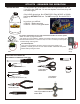
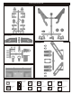
RTR KITS - REQUIRED FOR OPERATION THINGS NEEDED You will need to buy a few items to start the engine and run the car. • Use 20% nitro CAR fuel. Do not use airplane or heli fuels, they will over heat engine. • Buy LONG glow plugs, like OFNA/PICCO Plug (#51007 or 51008). Use plugs WITHOUT idle bar. Do NOT use plugs, like the MC-59 or OS-8 In your box you will find..
MUST READ THIS BEFORE RUNNING Running a nitro kit is fun and easy, but to make this a safe and good experience you must observe a few rules. This kit is extremely fast, easily over 40MPH, and can seriously injure someone if you are not careful. Where to run car? • Any running area you choose must be dry. Do not run car near any water or wet dirt. • Do not run on public streets. It is very easy to have the car run over or damaged by hitting the curb. • Do not operate car in tight confined places.
THINGS REQUIRED FOR OPERATION OPTION THINGS NEED BESIDES THE KIT OPTION PART 3.5 cc (21 Class) ENGINE REAR EXHAUST OFNA/Picco P7-EVO3 #51216 Glow Plug Heat with Battery & Charger # 10227....$$19.
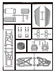
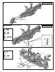
PLASTIC PARTS FOR USE 40047 RECEIVER BOX 40020 REAR LOWER ARM 40046 STONE GUARD 36081 REAR UPRIGHT 36901 FRONT KNUCKLEARM ARM 40003 DIFF.
PLASTIC PARTS FOR USE 40040 CENTER DIFF.
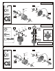
1 ASSEMBLY OF THE FRONT AND REAR DIFF. Builds two differentials for front and rear. Step 2 Step 1 40010 94034 4x4mm Set Screw .....x2 4x4 mm 40010 40009 P6 O-Ring 40513 .....x4 40009 40006 Oil 40010 2.5x13.8mm Pin .....x4 49032 36053 36053 Oil 40006 40003 40009 36053 8x16mm Ball Bearing .....x4 40513 2 ASSEMBLY OF THE FRONT AND REAR DIFF. 3x12mm Builds two differentials for front and rear. 30776 Step 1 Step 2 40513 30773 Tighten Tight the diff screws in this order.
4 ASSEMBLY OF THE CENTER DIFF. 3x12mm Step 1 30776 4x10mm Washer Step 2 40513 .....x4 30776 Tighten 30773 Tight the diff screws in this order. 94020 3x12mm Flat Head Hex Screw ....4 1 3 4 2 40011 30773 4mm Cross Pin .....X2 Diff. Oil Use 5000 weight diff. oil in the center. Fill the Diff. Case to approx. 80% with the Diff.Oil. 5 ASSEMBLY OF THE FRONT GEAR CASE Scre w Ce m ent 5x4mm Step 1 94036 5x4mm Set Screw Apply Grease .....x1 30080 40024 36053 40024 13x16x0.2mm Shim 94027 ..
7 ASSEMBLY OF THE FRONT LOWER ARMS Assembly for both right and left side. 90021 3mm E-Ring .....x4 3mm 36870 4x10mm Set Screw 4x10mm .....x2 40202 3mm 40524 8 ASSEMBLY OF THE FRONT UPPER ARMS Assembly for both right and left side. 2.5mm 90020 2.5mm E-Ring .....x4 40094 2.5mm 40094 36170 40094 9 ASSEMBLY OF THE KNUCKLE ARMS Assembly for both right and left side. Step 1 * L for left handside. 94034 4x4mm Set Screw L 36903 .....x2 36905 36904 36055 2.5x16.8mm Pin 36901 .....
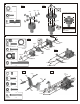
ASSEMBLY OF THE FRONT SUSPENSION ARMS Assembly for both right and left side. * Insert the drive shaft before assembling the knuckle arm. 11 ASSEMBLY OF THE FRONT STABILIZER Assembly for both right and left side. 94035 3x8mm Set Screw .....x2 30403 6mm Ball Makes two rods for left and right hand-side. .....x2 94005 3x16mm Hex Screw 40029 .....x2 30341 3x8mm 40029 30403 3x16mm 12 ASSEMBLY OF THE FRONT STABILIZER Screwnt Ceme 3x3mm 94033 3x3mm Set Screw S Cecrew me nt .....
13 ASSEMBLY OF THE SERVO SAVER Step 1 Step 2 40035 40037 40031 Plastic Flange Bushing 40031 40037 .....x2 40031 40031 49052 40031 40031 40033 40034 14 ASSEMBLY OF THE SERVO SAVER AND THE STEERING TIE-ROD 40027 Screw Cement Step 1 94041 3mm Nylon Nut Step 2 3x10mm Screw Cement 4x10mm 49051 .....x2 40031 3mm 3x10mm 94003 3x10mm Hex Screw 40039 40038 .....x2 36700 40038 94009 4x10mm Hex Screw 36790 .....x2 40036 94022 3x18mm Flat Head Hex Screw 3x18mm 40031 36700 1:1 .....
16 ASSEMBLY OF THE REAR GEAR CASE 94036 5x4mm Set Screw w t r e en Sc em C 5x4mm Step 1 4x12mm Step 2 40017 .....x1 94010 4x12mm Hex Screw .....x4 40027 4x12mm 30080 36053 36053 36053 8x16mm Ball Bearing 49012 .....x2 49049 40024 40024 40024 13x16x0.2mm Shim .....x2 4x16mm 4x45mm 94003 3x10mm Hex Screw 40017 .....x1 3x10mm 94011 4x16mm Hex Screw .....x2 94030 4x45mm Flat Head Screw 40015 4x45mm .....
19 ASSEMBLY OF THE WING STAY Step 1 94041 3mm Nylon Nut Step 2 .....x1 4x20mm 94042 4mm Nylon Nut 4x16mm .....x2 3mm 94011 4x16mm Hex Screw .....x2 4mm Nylon Nut 4x16mm 94012 4x20mm Hex Screw 3x25mm .....x4 40018 94008 3x25mm Hex Screw .....x1 20 ASSEMBLY OF THE REAR LOWER ARMS Assembly for both right and left side. Step 1 90020 2.5mm E-Ring Step 2 40020 .....x4 36082 36081 40020 94036 5x4mm Set Screw 40020 .....x2 2.5mm 36055 36053 36055 2.5x16.8mm Pin .....x2 30656 36053 2.
22 ASSEMBLY OF THE REAR SUSPENSION ARMS Assembly for both right and left side. 3mm Nylon Nut Assembly of the rear upper arm. 94041 3mm Nylon Nut 40065 .....x4 36861 36850 36850 7mm Ball 40065 .....x4 36850 94006 3x18mm Hex Screw .....x2 3mm Nylon Nut 3x18mm 94008 3x25mm Hex Screw .....x2 1:1 *Approx. 13mm 3x25mm 36111 *Insert the drive shaft before assembly the upper arms. 23 ASSEMBLY OF THE REAR STABILIZER Assembly for both right and left side. Makes two rods for left and right hand-side.
25 ASSEMBLY OF THE CENTER DIFF. MOUNT Step 1 Step 2 Step 3 40040 40042 40512 40040 40512 40042 26 ASSEMBLY OF THE BRAKE DISK INTO CENTER DIFF. MOUNT Step 1 A B Step 3 C 36661 36660 * Place the brake disc between the brake disc pads. Step 2 C B * Remove the double-side tape before assembly. 40040 Brake disc A double-side tape 40044 36661 40045 27 ASSEMBLY OF THE CENTER DIFF. MOUNT *Approx. 8mm *8 ¬ù m Step 1 Step 2 3x12mm Approx.
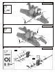
31 ASSEMBLY OF THE STONE GUARD 28 Assembly for both right and left side. 40064 94003 3x10mm Hex Screw 40046 .....x6 40046 3x10mm 3x10mm 3x10mm 29 ASSEMBLY OF THE FRONT GEAR CASE ONTO CHASSIS 94039 4x10mm Flat Head Hex Screw .....x2 40013 94026 4x12mm Flat Head Hex Screw .....x2 94027 4x16mm Flat Head Hex Screw .....x4 4x10mm 4x12mm 4x16mm 30 ASSEMBLY OF THE CENTER DIFF. ONTO CHASSIS *Insert the drive shaft into the cap joint before assembly the center diff. onto chassis. 94046 2.
31 ASSEMBLY OF THE REAR GEAR CASE ONTO CHASSIS *Insert the drive shaft into the cap joint before assembly rear gear box onto chassis. 94026 4x12mm Flat Head Hex Screw .....x2 94027 4x16mm Flat Head Hex Screw .....x4 40028 4x16mm 4x12mm 32 ASSEMBLY OF THE RADIO TRAY 3x12mm Step 1 3x10mm 3x12mm Step 2 3x8mm 3x10mm 3x10mm 94040 3x8mm Washer 3x8mm 3x12mm .....x8 3x8mm 94003 3x10mm Hex Screw .....x6 94004 3x12mm Hex Screw .....
34 ASSEMBLY OF THE STEERING SERVO AND STEERING ROD 1:1 *Approx. 18.5mm 30403 6mm Ball .....x2 94003 3x10mm Hex Screw * Use the screw provided with your servo . .....x1 30401 30661 30342 30403 30403 30401 3x10mm 35 ASSEMBLY OF THE RADIO TRAY AND STICK PACK BATTERY Step 1 Step 2 40130 94003 3x10mm Hex Screw .....x2 3x10mm 37410 3x10mm Battery Case 37410 40130 40130 36 ASSEMBLY OF THE RADIO TRAY ONTO CHASSIS 3x12mm 3mm Nut .....x1 94019 3x10mm Flat Head Hex Screw .....
37 ASSEMBLY OF THE FUEL TANK ONTO CHASSIS Step 1 Step 2 3x10mm 3x10mm Flat Head Hex Screw .....x2 3x10mm 3x10mm Hex Screw 40066 .....x2 40047 Do Not Over Tighten 3x10mm 40047 38 ASSEMBLY OF THE CLUTCH Step 1 Step 2 10010 10040 38313 S Cecrew me nt *Fit the flywheel using a pair of the plIer and cross wrench. 10098 10101 39 ASSEMBLY OF THE CLUTCH AND ENGINE MOUNT *Place the clutch shoes with the clutch springs over the 3 pins of the flywheel.
40 ASSEMBLY OF THE ENGINE ONTO CHASSIS Note book Paper. 10114 5mm Engine Mount Screw *Use note book paper to set gear backlash between spur gear and clutch bell gear, applying pressure while retightening the engine. *If the space is not correct the spur gear will be damaged. .....x4 10114 41 ASSEMBLY OF THE MANIFOLD AND MUFFLER Step 1 Step 2 10060 94036 5x4mm Set Screw .....x2 49055 10185 94039 4x10mm Flat Head Hex Screw .....
43 ASSEMBLY OF THE THROTTLE LINKAGES INTO LEVER 3x3mm 94033 3x3mm Set Screw .....x2 10300 10300 5mm Fuel Tube Snap On * Use the screw provided with your servo . 10769 44 ADJUSTING THE ENGINE CONTROL LINKAGES (Neutral) (Brake) (Throttle High) Approx. 0.5mm Idling adjusting Screw Approx. 1mm gap Carburetor is Opening fully Turn on the Transmitter then Receiver and set the Engine Control Servo Trim to the neutral position. Adjust the idling adjusting screw on the Carburetor to be open approx.
46 ASSEMBLY OF THE FRONT SHOCKS *Assemble 2 for front CORRECT SHOCK ASSEMBLY Step 2 Fit the o-ring into groove before assembly 41012 1mm Washer .....x2 40060 41006 2.6x5mm 41008 41011 40113 41012 2.6x5mm 41007 41006 N.B. Do not over tighten as the plastic will strip. 41012 41012 41012 3.5mm O-Ring Carefully screw the shock shaft into the bottom of the plastic ball and until the distance between the ballend and the shock body is 28mm for the front. 28mm Step 1 40054 .....
48 ASSEMBLY OF THE FRONT SHOCK ABSORBER 94041 3mm Nylon Nut .....x2 94040 3x8mm Washer .....x2 40643 94007 3x20mm Hex Screw 3mm .....x2 3x8mm 3x20mm Assembly for both right and left side. 49 ASSEMBLY OF THE REAR SHOCK ABSORBER 94041 3mm Nylon Nut .....x2 94040 3x8mm Washer .....x2 40643 94007 3x20mm Hex Screw 3mm .....x2 3x8mm 3x20mm Assembly for both right and left side. 50 ASSEMBLY OF THE FUEL TUBE Connect to carbulater. Connect to pressure nipple. Connect to fuel nipple.
51 ASSEMBLY OF THE WING 3x12mm 40027 40027 Body Reamer (Not included) 94041 3mm Nylon Nut .....x2 94004 3x12mm Hex Screw .....x2 16015 3mm 3mm Drill two 7mm holes for mounting. 52 ASSEMBLY OF THE TIRES AND WHEELS Step 1 Step 2 Apply instant glue into the groove of the wheel. 81095 IN S G TA L N U T E 86056 86082 53 ASSEMBLY OF THE TIRE ONTO FRONT KNUCKLE AND REAR HUB Assembly for both right and left side. 40550 40550 40550 Wheel Nut .....x4 Tire and Wheel assembly.
54 ASSEMBLY OF THE BODY AND PAINTING Use a neutral detergent to remove any dirt and oil. Cut out the body as shown. Mask the windows from the inside with masking tape. Apply internal color decals from the inside and paint the body with polycarbonate spray paints. Spray Paint Cutting holes. *Make a 8mm hole for body mount.* *Make a 8mm hole for body mount. Cut out for engine. *Hole for engine. *Hole for fuel tank. *Hole for antenna pipe. *For the exhaust outlet of the muffler.
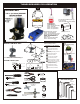
55 MOUNTING BODY 31159 Body Clips 31159 Body Clips 56 STARTING OF THE ENGINE How to start the engine: 1. Turn on transmitter and then receiver. 2. Fill fuel tank with fuel bottle. 3. Connect 1.2V glow plug starter. 4. Start engine with 12V starter. ( Note the direction of the starter.) 5. After the engine be started, remove the 1.2V glow plug starter. 12V Starter and Starter Ring ( Not Included) Starter rubber ring for car. ( Insert starter rubber ring on the 12V starter.) Glow Plug (Not Included) 1.
34952 Picco off-road parts list OFNA 10010 10040 10060 10069 10098 10101 10114 10120 10177 10185 10270 10282 10300 10399 16015 30080 30171 30172 30213 30341 30342 30401 30403 30480 30531 30560 30656 30661 30773 30776 30802 31159 31990 34053 34110 36053 36055 36081 36082 36111 36140 36170 36660 36661 36700 36790 36850 36861 36901 36903 36904 36905 37410 38313 40001 40003 40005 40006 40009 40010 40011 40013 40015 40016 40017 40018 40019 40020 40024 40027 DESCRIPTION CLUCTH SHOES BLACK 3PCS 3 PIN FLYWHEEL, .
SETTING GUIDE FRONT CAMBER ANGLE SETTING + Positive - - REAR CAMBER ANGLE SETTING + + Positive Negative - - Place the model car on flat surface. Raise the chassis to it's maximum clearance before the wheels leave the ground. Adjust the length of the front and rear upper arms so that the wheels are right angle to the ground. The camber angle adjustment can be moving the turnbuckle rod on the upper arms, clockwise or anti-clockwise. (We suggest use zero degree for the front and 1.
OWNER’S REGISTRATION CARD OFNA Racing congratulates you on your purchase of our fine OFNA Product. With proper maintenance and handling this kit will provide many hours of enjoyment. The registration card should be filled out and mailed to OFNA Racing within 10 days of purchase date.