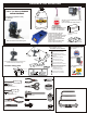
ULTRA GTP II INSTRUCTION MANUAL #34316 #34317 ADDITIONAL PARTS NEEDED * Batteries 8 AA for Radio * Receiver Batteries (10202 Hump Pack) * Model Fuel 20% Nitro * CA Glue THIS IS NOT A TOY ! This kit is extremely fast, and can easily go over 40mph and can seriously injured someone. If you are under 18years of age have and adult supervision.
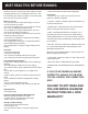
MUST READ THIS BEFORE RUNNING Running a nitro kit is fun and easy, but to make this a safe and good experience you must observe a few rules. This kit is extremely fast, easily over 40MPH, and can seriously injure someone if you are not careful. Where to run car? • Any running area you choose must be dry. Do not run car near any water or wet dirt. • Do not run on public streets. It is very easy to have the car run over or damaged by hitting the curb. • Do not operate car in tight confined places.
REQUIRED FOR OPERATION THINGS NEED BESIDES THE KIT 3.5 cc (21 Class) ENGINE REAR EXHAUST OFNA/Picco (Option Parts) P-9R EVO #51219 Glow Plug Long Heat with Battery & Charger # 10215....$27.
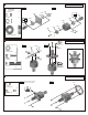
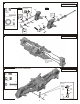
1 ASSEMBLY OF THE FRONT AND REAR DIFF. Builds two differentials for front and rear. Step 2 Step 1 30779 2x12.8mm Pin 30769 .....x4 30751 30779 30777 30901 Oil 94034 4x4mm Set Screw .....x2 30620 30620 30751 Oil 30777 P5 O-Ring 30901 .....x4 30769 30777 30779 30779 4X4mm 30620 7x19x6mm Ball Bearing .....x4 2 ASSEMBLY OF THE FRONT AND REAR DIFF. Builds two differentials for front and rear. Tighten Step 1 Step 2 30773 30769 30776 3x12mm Tight the diff. screws in this order.
4 ASSEMBLY OF THE GEAR BOX AND FRONT SHOCK STAY Step 1 Step 2 5x5mm 94036 5x4mm Set Screw .....x1 ew t Scermen C 30010 30630 30082 30262 30630 6x13x5mm Ball Bearing Apply Grease .....x2 30630 4x10mm 30130 30010 94009 4x10mm Hex Screw .....x2 3x25mm 94023 3x25mm Flat Head Screw .....x2 94029 4x25mm Flat Head Screw .....x2 4x25mm 5 ASSEMBLY OF THE FRONT LOWER ARMS 3mm 3mm 36870 4x10mm Set Screw .....x2 Ensure Free Movement 94011 4x16mm Hex Screw 36171 4x10mm 36890 .....
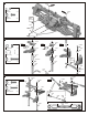
7 ASSEMBLY OF THE FRONT KNUCKLE ARMS Assembly for both right and left side. Step 1 Step 2 *Notice the direction of the plastic washer. 36901 94036 5x5mm Set Screw .....x2 Ensure Free Movement 36903 36055 2.5x16.8mm Pin L 36905 .....x2 Do Not Over Tighten 36052 36053 36903 36904 36053 36053 8x16x5mm Ball Bearing .....x4 30656 36905 Do Not Over Tighten S Cecre m w en t 5x4mm 36055 8 ASSEMBLY OF THE FRONT KNUCKLE AND FRONT SUSPENSION ARMS Assembly for both right and left side.
10 ASSEMBLY OF THE FRONT STABILIZER 94033 3x3mm Set Screw .....x2 94002 3x8mm Hex Screw .....x2 3x3mm Screw t Cemen S Cecrew me nt 3x3mm Ensure Free Movement 30261 94040 3x8x0.8mm 3x8mm 11 ASSEMBLY OF THE SERVO SAVER 36740 36740 Step 1 Step 2 Step 3 3x16mm 94041 M3 Nylon Nut 36743 6mm E-Ring 94005 3x16mm Hex Screw .....x2 36743 6mm 36740 36742 36740 36743 6mm 36741 .....x4 36740 Ensure Free Movement 8x12x1mm 30361 .....
13 ASSEMBLY OF THE SERVO SAVER ONTO THE FRONT GEAR BOX 94041 M3 Nylon Nut .....x2 3x15mm 94003 3x10mm Hex Screw .....x2 94021 3x15mm Flat Head Screw .....x2 3mm 3x10mm 40039 3x15mm 3mm 40039 14 ASSEMBLY OF THE GEAR BOX AND REAR SHOCK STAY Step 1 Step 2 5x5mm 94036 5x5mm Set Screw .....x1 ew t Scermen C 3mm 30010 30630 34009 30082 30630 6x13x5mm Ball Bearing .....x2 Apply Grease 30630 3x16mm 30130 30010 94005 3x16mm Hex Screw .....x2 94022 3x18mm Flat Head Screw .....
16 ASSEMBLY OF THE REAR SUSPENSION ARMS 94036 5x5mm Set Screw Assembly for both right and left side. 36081 36055 .....x2 36082 36053 94001 3x4mm Hex Screw 5x5mm .....x2 36053 36054 40028 36053 8x16x5mm Ball Bearing .....x4 36055 2.5x16.8mm Pin .....x2 3x4mm 34055 34035 17 ASSEMBLY OF THE REAR SUSPENSION ARMS Step 1 36850 7mm Ball .....x4 3mm Step 2 40065 .....x4 94041 3mm Nylon Nut Ensure Free Movement 40065 36850 36861 94006 3x18mm Hex Screw .....
19 ASSEMBLY OF THE REAR STABILIZER 94033 3x3mm Set Screw .....x2 94022 3x8mm Hex Screw .....x2 3x3mm ewnt Scrm e Ce S Cecre m w en t 3x3mm Ensure Free Movement 34027 3x8x0.8mm 3x8mm 20 ASSEMBLY OF THE REAR BODY POST Step 1 Step 2 3mm 31159 M2 Nut Choose the correct body post pin hole for your body. 33011 .....x2 94041 M3 Nylon Nut 3mm 33011 .....x2 33011 31159 2x18mm Screw .....x2 94005 3x16mm Hex Screw 3x16mm 33010 .....
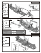
22 ASSEMBLY OF THE TWO SPEED TRANSMISSION INTO THE CENTER MOUNT Step 1 Step 2 30170 30201 94036 5x5mm Set Screw .....x2 30620 5x5mm 30620 30201 30620 7x19x6mm Ball Bearing 40218 8x12x1mm 30202 .....x2 30170 5x5mm 30202 23 ASSEMBLY OF THE BRAKE DISK INTO CENTER DIFF. MOUNT 3x12mm Step 1 94033 3x3mm Set Screw 94004 3x12mm Hex Screw 94005 3x15mm Hex Screw Step 2 * Remove the double-side tape before assembly. 36660 36661 .....x1 30652 3x3mm 30211 30171 30213 double-side tape .....x4 0.
25 ASSEMBLY OF THE BRAKE DISK INTO SINGLE SPEED MOUNT 3x12mm Step 1 94033 3x3mm Set Screw 30652 36660 36661 .....x1 Step 2 * Remove the double-side tape before assembly. 3x3mm 30211 30213 94004 3x12mm Hex Screw 94005 3x15mm Hex Screw double-side tape .....x4 0.5mm *Leave a 0.5mm space between brake disk and brake pad. .....x2 3x15mm 36650 26 ASSEMBLY OF THE FRONT GEAR CASE ONTO CHASSIS 94019 3x10mm Flat Head Hex Screw .....x2 94026 4x12mm Flat Head Hex Screw .....
28 ASSEMBLY OF THE REAR GEAR CASE ONTO CHASSIS 94027 4x16mm Flat Head Hex Screw .....x4 *Insert the drive shaft into the cap joint before assembly rear gear box onto chassis. 34050 94023 3x25mm Flat Head Hex Screw .....x2 4x16mm 3x25mm 4x16mm 29 ASSEMBLY OF THE STONE GUARD ONTO CHASSIS 34080 94019 3x10mm Flat Head Hex Screw .....x6 3x10mm 3x10mm 3x10mm 30 ASSEMBLY OF THE FRONT SERVO AND RADIO TRAY Step 1 3x10mm Step 2 3x10mm 34026 94003 3x10mm Hex Screw 34026 .....
31 ASSEMBLY OF THE FRONT SERVO AND RADIO TRAY 3x12mm 3x8x0.8mm Step 1 Step 2 3x10mm 94003 3x10mm Hex Screw .....x4 94004 3x12mm Hex Screw .....x4 3x10mm 34013 34026 32 ASSEMBLY OF THE RADIO TRAY AND RECEIVER BOX 30560 Step 1 *Use the screw provided with your switch Step 2 3x10mm 2X8mm Screw 3x10mm .....x2 30647 34013 3x10mm 94003 3x10mm Hex Screw .....x6 10282 Receiver Switch Battery *Put the servo wire into receiver box and connect to receiver.
34 ASSEMBLY OF THE STEERING SERVO AND STEERING ROD Step 1 Sanwa/Airtronics 3x12mm Hex Screw S .....x2 HiTech Futaba JR J F H * Choose the right servo horn adapter for your servo. 30403 6mm Ball Step 2 .....x1 3x12mm 30403 30411 6mm Ball and Socket 3x12mm .....x1 30661 30401 38280 Turnbuckle Use the screw provided with your servo. 23mm 0 5 10 15 20 30401 25 30411 35 ASSEMBLY OF THE FUEL TANK ONTO THE CHASSIS Step 1 Step 2 3x12mm 3x10mm Flat Head Hex Screw .....
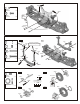
37 ASSEMBLY OF THE CLUTCH (For two speed.) Step 1 10099 3x8x0.8mm Washer Step 3 .....x1 35253 35242 w t r e en Sc em C 10099 5x9x0.3mm Washer .....x1 (Fortsingle speed.) 35958 5x8x2.5mm Ball Bearing .....x1 Step 2 10402 34110 Tighten 34110 w t r e en Sc em C 3x5mm S Ce cr m ew en t 35238 10099 3x5mm Cap Screw 5x9x0.3mm 3x8mm 34110 5x10x4mm Ball Bearing .....x1 35958 3x7mm 3x5mm .....x1 *Use washers or shims for the clutch bell, this may vary with different engines.
40 ASSEMBLY OF THE MUFFLER ONTO CHASSIS 94036 5x5mm Set Screw 94042 4mm Nylon Nut .....x1 .....x1 10069 94026 4x12mm Flat Head Screw .....x1 10120 5x5mm 4mm 30491 4x12mm 41 ASSEMBLY OF THE THROTTLE LINKAGE Step 1 Step 3 30172 94033 3x3mm Set Screw 30802 2x4mm 2x7mm .....x3 30802 3x3mm 2mm Nut 3x10mm .....x2 3x3mm 10300 2x25mm 2x4mm Screw 2x8mm Screw 30531 3x3mm 36140 .....x1 30802 30802 2x8mm 10300 Step 2 .....x2 2x25mm Screw .....x1 2mm 94003 3x10mm Hex Screw .....
43 ADJUSTING THE ENGINE CONTROL LINKAGES (Neutral) (Throttle High) (Brake) Approx. 0.5mm ¬ 0 .5 mù 10300 Idling adjusting Screw 10300 Approx. 1mm gap Turn on the Transmitter then Receiver and set the Engine Control Servo Trim to the neutral position. Adjust the idling adjusting screw on the Carburetor to be open approx. 1mm gap. Adjust both of the 10300 Engine Control and Brake linkage accordingly. Adjust the Engine while it is not running.
46 ASSEMBLY OF THE FRONT AND REAR SHOCK SPRING * Assemble 2 Sets for Front * Assemble 2 Sets for Rear 30274 30275 40643 40643 47 ASSEMBLY OF THE FRONT SHOCK ABSORBER 3x25mm 94041 3mm Nylon Nut .....x2 94007 3x20mm Hex Screw .....x2 40531 94040 3x8mm 90018 3x25mm Cap Screw 3mm .....x2 Do Not Over Tighten 3x20mm Assembly for both right and left side. 48 ASSEMBLY OF THE REAR SHOCK ABSORBER 94041 3mm Nylon Nut .....x2 94007 3x20mm Hex Screw .....
49 ASSEMBLY OF THE FRONT BUMPER Choose the correct body post pin hole for your body. 33011 33011 Step 1 Step 2 31159 2mm 33011 M2 Nut .....x2 2x18mm 34091 2x18mm Screw .....x2 94010 4x12mm Hex Screw 33011 .....x2 34090 94011 4x16mm Hex Screw .....x4 4x12mm 4x16mm 50 ASSEMBLY OF THE AIR FILTER Step 2 Step 1 40128 Choose the correct body post pin hole for your body. 3x8mm 40127 *Apply filter oil to the foam before use. 40129 A-81 40127 94002 3x8mm Hex Screw .....
52 ASSEMBLY OF THE TIRES AND WHEELS 86050 *Pull back the tire bead slightly and spot glue in four spots as shown. When dry, glue the rest of the wheel between the spots. Repeat the procedure on the other side of the wheel until fully glued. Contact Adhesive 10239 IN ST GL ANT UE Contact Adhesive 86026 86059 Inner Sponge (WidE) 86059 Inner Sponge (Narrow) 53 ASSEMBLY OF THE WHEELS ONTO THE FRONT KNUCKLE AND REAR HUB Assembly for both right and left side. 40550 40550 Wheel Nut .....
55 ASSEMBLY OF THE REAR WING Doubleside Tape Nylon Screw Do Not Over Tighten Take off the doubleside paper before assembly. Side Plate Doubleside Tape Side Plate Nylon Nut * Take the side plate as picture shown.
57 STARTING OF THE ENGINE How to start the engine: 1. 2. 3. 4. Turn on transmitter and then receiver. Fill fuel tank with fuel bottle. Connect 1.2V glow plug igniter . Start engine with a 12V starter. ( Note the direction of the starter.) 5. After the engine has started, remove the 1.2V glow plug igniter . A 12V Starter and Starter Ring ( Not Included) Starter rubber ring for car. ( Insert starter rubber ring on the 12V starter.) Glow Plug (Not Included) 1.
OPERATING YOUR MODEL SAFELY Before Running Your radio control model can move at high speed and therefore can cause injury to people or damage property. It is your responsibility to operate your model safely. Engine Start-Up While Running Cautions for Safety For engine use, refer to the manual included with the engine. Check that the model turns in proportion to the amount you move the steering control of the transmitter. Do not run your model through water. This may cause rust or electrical problems.
SETTING GUIDE FRONT TOE-IN AND TOE-OUT SETTING Use a 5mm allen wrench to adjust toe-in for front . (Front) Adjust the length of the front steering rod to change the toe angle. NEUTRAL POSITION Making the steering rod longer will make the front tires become toe-in. Response will be slower and will over steer. TOE-IN TOE-OUT TOE-OUT Making the steering rod shorter will make the front tires become toe-out. Response will be quicker and will under steer. We recommended adjusting the front toe-out to 1.
Parts List for Ultra-GTP, 911 RTR .
BLANK
OWNER’S REGISTRATION CARD OFNA Racing congratulates you on your purchase of our fine OFNA Product. With proper maintenance and handling this kit will provide many hours of enjoyment. The registration card should be filled out and mailed to OFNA Racing within 10 days of purchase date.