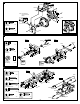
IMPORTANT-READ THIS BEFORE RUNNING 1.Before Starting •Please read manual carefully (With a parent, guardian or a responsible adult if necessary). 2.While Operating •Any running area you choose must be dry. Do not run vehicle near any water or wet areas. •Do not run on public streets. It is very easy to have the car run over or be damaged by hitting the curb. •Do not operate the car in tight confined places. The vehicle is very fast and will easily hit something. •Do not run near people or animals.
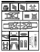
OVERVIEW OVERVIEW Components Radio Control Car Parts Bag TOOLS NOT INCLUDED IN THE KIT Screw Cement Screw Cement CA Instant Cemment Body Reamer GEAR GREASE Cutter Curved Scissors Gear Grease Craft Knife Needle Nosed Pliers Precision Caliper Equipment Needed UM-3 "AA" type Batteries ( 8pcs ) Transmitter Brushless Electric Speed Controller Brushless Motor Servo 7.
PLASTIC PARTS FOR USE 30751 DIFF. CASE 30751 DIFF. CASE FRONT & REAR 40536 FRONT C HUB 30761 DIFF. CASE CENTER 34063 REAR LOWER ARM 30010 FRONT AND REAR GEAR BOX 30657 FRONT LOWER ARM 36020 FRONT UPPER ARM 30351 REAR LOWER ARM HOLDER 30240 BUMPER 40643 SHOCK PLASTIC PARTS 40643 Shock Plastic Ball End (Long) 30160 FRONT LOWER ARM HOLDER 30201 CENTER DIFF.
PLASTIC PARTS FOR USE 30686 FRONT STIFFENER 30674 SERVO SAVER 30270 WING STAY 16015 WING 41033 STONE GUARD 30662BATTERY CASE SYMBOLS USED THROUGHOUT THE INSTRUCTION MANUAL Degrease With Motor Spray Parts Bag Used Do Not Over Tighten Tighten BAG Do Not Over Tighten Screw Cement Apply Screw Cement Apply Oil Oil Ensure Free Movement True-To-Scale Time 1:1 Time Contact Adhesive Contact Adhesive Tighten Apply Lubricant Apply Grease Ensure Free Movement Pay attention here
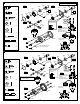
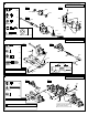
1 ASSEMBLY OF THE FRONT AND REAR DIFF. Build two differentials for front and rear. 30901 Step 1 Step 2 30901 30620 94034 4x4mm Set Screw 30620 30751 30751 .....x2 Oil 30121 3x5mm Screw 94004 3x12mm Hex Screw 30769 .....x8 30777 30779 4x4mm 30769 30780 .....x8 Notice the straight holes are for the front and rear only. Step 3 30773 30777 P5 O-Ring Oil 30777 30780 Tighten 3x12mm 30769 .....x4 Step 4 30776 Apply diff. gear grease to the differential, during assembly. Fill the diff.
3 ASSEMBLY OF THE CENTER DIFF. MOTOR MOUNT Screw t Cemen Screw t Cemen 3x10mm 3x12mm 30653 Note: The width of the holes for front diff. Mount. 30675 94003 3x10mm Hex Screw .....x2 94004 3x12mm Hex Screw .....x2 30201 4 ASSEMBLY OF THE FRONT GEAR CASE Screw Cement Step 1 Step 2 5x4mm 4x12mm 94036 5x4mm Set Screw 30673 30082 .....x1 30630 30010 94010 4x12mm Hex Screw .....x2 30630 30130 30630 6x13x5mm Ball Bearing .....
6 ASSEMBLY OF THE KNUCKLE ARMS Assemble both right and left side. Step 1 94034 4x4mm Set Screw Step 2 40520 .....x2 36053 4mm 36053 94042 4mm Nylon Nut .....x4 Step 3 40536 34053 40528 40527 Knuckle Arm Bushing .....x4 4mm 36055 40528 King Pin Screw 40527 .....x4 40527 30656 36055 2.5x16.8mm Pin .....x2 4x4mm 8x12x0.3mm 40218 .....x2 8x12x0.3mm Washer Screw Cement 7 ASSEMBLY OF THE FRONT SUSPENSION ARMS Assemble both right and left side. Step 1 36870 4x10mm Set Screw .....
9 ASSEMBLY OF THE FRONT STABILIZER Assemble both right and left side. Step 1 94033 3x3mm Set Screw .....x2 94035 3x8mm Set Screw .....x2 94002 3x8mm Hex Screw .....x2 Step 2 3x3mm 94006 3x18mm Hex Screw 3x8x0.8mm 30341 .....x2 40199 3x18mm 3x8mm 34027 3x8x0.8mm 94040 3x8x0.8mm Washer .....x2 40199 30403 3x8mm Makes two rods for left and right hand-side 10 ASSEMBLY OF THE SERVO SAVER Step 1 Step 2 Step 3 3x16mm 94041 3mm Nylon Nut .....x2 94005 3x15mm Hex Screw .....
12 ASSEMBLY OF THE SERVO SAVER ONTO GEAR CASE Step 1 Step 2 3x15mm 3x15mm Screw Cement 40039 3x10mm 94003 3x10mm Hex Screw .....x2 40039 3x15mm 94021 3x15mm Flat Head Hex Screw Screw Cement .....x4 40039 3mm Tapered Washer(Alum.) .....x4 40039 13 ASSEMBLY OF THE REAR GEAR CASE Step 2 Step 1 w t Scre en Cem 5x4mm 30630 30082 94036 5x4mm Set Screw .....x1 30630 Apply Grease 30630 6x13x5mm Ball Bearing 30010 30130 .....
15 ASSEMBLY OF THE REAR GEAR CASE Step 1 Step 2 41009 3x20mm 34033 30270 94019 3x10mm Flat Head Hex Screw .....x1 30270 41010 94006 3x18mm Hex Screw 41009 3x18mm .....x2 30270 30270 3x10mm 94007 3x20mm Hex Screw 41009 3x28mm Cap Screw 30270 .....x4 30270 41010 3x20mm 30270 3x18mm .....x2 16 ASSEMBLY OF THE WING STAY AND REAR WHEEL HUB *Builds two rear wheel hubs for use. Step 2 Step 1 94036 5x4mm Set Screw .....x2 3mm 94011 4x15mm Hex Screw 36082 .....
18 ASSEMBLY OF THE REAR LOW ARMS INTO GEAR BOX Assemble both right and left side. Step 1 94041 3mm Nylon Nut .....x4 90021 3mm E-Ring .....x4 Step 2 3x18mm 3mm 3x25mm 3mm 94006 3x18mm Hex Screw .....x2 94008 3x25mm Hex Screw .....x2 3mm 36171 3mm 34054 19 ASSEMBLY OF THE REAR STABILIZER 3x8x0.8mm 94002 3x8mm Hex Screw .....x2 34027 3x8x0.8mm 94040 3x8x0.8mm Washer .....x2 3x8mm 20 ASSEMBLY OF THE REAR STABILIZER RODS Assemble both right and left side.
21 ASSEMBLY OF THE FRONT GEAR CASE ONTO CHASSIS 94019 3x10mm Flat Head Hex Screw .....x2 30240 94023 3x25mm Flat Head Hex Screw .....x2 94026 4x12mm Flat Head Hex Screw .....x2 30676 4x12mm 94027 4x16mm Flat Head Hex Screw 4x16mm 3x10mm .....x4 4x16mm 3x25mm 22 ASSEMBLY OF THE CENTER DIFF. ONTO CHASSIS Insert drive shaft into cap joint before assembly center diff. 36100 (90mm) 94026 4x12mm Flat Head Hex Screw .....x3 4x12mm 94027 4x16mm Flat Head Hex Screw 4x16mm .....
23 ASSEMBLY OF THE REAR GEAR CASE ONTO THE CHASSIS Insert drive shaft into cap joint before assembling center diff. 94023 3x25mm Flat Head Hex Screw 36100 (86.5mm) .....x2 4x16mm 3x25mm 94027 4x16mm Flat Head Hex Screw 4x16mm .....x4 24 ASSEMBLY OF THE STONE GUARD Assemble both right and left side. 41033 3x10mm 94019 3x10mm Flat Head Hex Screw 3x10mm .....
25 ASSEMBLY OF THE REAR CENTER BRACE 3x12mm 30686 30686 4x20mm 4mm 94042 4mm Nylon Nut .....x2 94004 3x12mm Hex Screw .....x2 94012 4x20mm Hex Screw .....x1 94027 4x16mm Flat Head Hex Screw .....
27 ASSEMBLY OF THE ELECTRIC SPEED CONTRTOL Double side tape (Not Included) Electronic Speed Control (not included) 28 ASSEMBLY OF THE BATTERY TRAY BRIDGE ONTO BATTERY CASE 3x8mm 3x10mm 30662 94002 3x8mm Hex Screw .....x2 94003 3x10mm Hex Screw .....
30 ASSEMBLY OF THE STEERING SERVO ONTO RADIO CASE 3x10mm 3x8x0.8mm 3x10mm 3x8x0.8mm Steering Servo (Not Included) 94003 3x10mm Hex Screw .....x4 30662 94040 3x8x0.8mm Washer .....x4 31 ASSEMBLY OF THE SERVO WIRE INTO RADIO CASE 32 ASSEMBLY OF THE BATTERY CASE ONTO CHASSIS 94019 3x10mm Flat Head Hex Screw .....x3 94026 4x12mm Flat Head Hex Screw .....x1 94053 5x10mm Flat Head Hex Screw .....
33 ASSEMBLY OF THE RADIO CASE ONTO CHASSIS 3x10mm 3x10mm 94019 3x10mm Flat Head Hex Screw .....x4 34 ASSEMBLY OF THE RECEIVER INTO RADIO CASE 30560 Antenna Wire 3x8mm 40642 Please carefully read the Receiver Instruction Manuals before installation. 37410 30662 *Plug in your speed controller wire to CH2 and steering servo wire to CH1 of your receiver. 30662 Do not cut or shorten antenna wire.
36 MOTOR INSTALL Electric Motor (Not Included) 30670-(12T) 30664-(13T) 30665-(14T) 30666-(15T) 30667-(16T) 30668-(17T) Step detail *Approx. 20mm 4x4mm 94034 4x4mm Set Screw .....x1 37 MOTOR INSTALL 94038 3x12mm Cap Screw Do Not Over Tighten .....x2 3x12mm 3x8x0.8mm 94040 3x8x0.8mm Washer Ensure Free Movement .....x2 38 ADJUST MOTOR AND SPUR GEAR MAINTENANCE Tighten the 3x12mm screw temporary.
39 ASSEMBLY OF THE SHOCKS Assemble both left and right sides. 40060 40060 2.6x6x0.5mm 2.6x6x0.5mm Step detail 41011 41011 2.6x6x0.5mm 2.6x6x0.5mm Hold the shock rod at top of exposed thread with side cutting needle nosed pliers. Be careful not to damage the shock shaft. Do Not Over Tighten 40054 (SHORT) 40055 (LONG) Use tools to tighten as shown. Step detail 40060 2.6mm Nylon Nut .....x2 94059 2.6x6x0.5mm Washer .....
42 ASSEMBLY OF THE SHOCKS Assemble both left and right sides. Step 1 41007 Step 2 Oil Oil 41006 Oil Step detail Fit the o-ring into groove before assembly. TOP 41007 P10 O-RING .....x4 REAR SHOCK FRONT SHOCK 43 ASSEMBLY OF THE SHOCKS Assemble both left and right sides. 30403 Step detail 40643 30403 Step detail Do Not Over Tighten 37.5mm 28mm 40643 Do Not Over Tighten Attention distance. 14mm 30403 6mm Ball .....
45 SETTING THE SHOCK REBOUND TO 50% & 0% (MEDIUM REBOUND & LOW REBOUND) TIGHTENED HALF WAY 50% Step 1 TIGHTENED 100% Step 2 TIGHTENED HALF WAY 50% Step 3 50% Step 1 TIGHTENED 100% Step 2 Step 3 50% 46 ASSEMBLY OF THE SHOCKS SPRING Step 2 Step 1 Step 3 Step 1 Step 2 40058 41015(SHORT) 41015(LONG) Cut 7mm 41008 40058 FRONT SHOCK 41008 REAR SHOCK 47 ASSEMBLY OF THE SHOCKS INTO THE SHOCK STAY 40643 40643 94041 3mm Nylon Nut .....x4 3mm 3x8x0.8mm 94040 3x8x0.8mm Washer 3mm .....
48 ASSEMBLY OF THE TIRES AND WHEELS IN S G TA L N U T E Step 1 Step 2 Make four tires that are the same. 80025 Step detail IN S G TA L N U T E Agglutination place Step 3 Use " Instant glue " and draw a round the rim where it attaches the tire . When it is dry glue the other side of the rim. Repeat the step and ensure the rim and tire are fully glued. 86056 49 ASSEMBLY OF THE TIRE ONTO THE FRONT KNUCKLE AND REAR HUB Assemble both left and right sides.
51 BATTERY INSTALL If use hard case battery , make a hole as picture shown. 15mm 8mm Follow the manual instruction provided by ESC manufacturer to install the wire. 52 MAKING HOLES AND CUTTING ON THE BODY SHELL Step 1 Body Reamet (not included) 10806 BLACK 10807 BLUE Step 2 For electric speed control cooling hole. Make 6mm hole 31143 Make 7.5mm holes on the body, Body Mount as shown. Cut the body shelll as shown.
54 PAINTING BODY SHELL Mask the windows on the inside with masking tape. 55 PAINTING BODY SHELL Paint the body with polycarbonate spray paints. Sp ray Pa in t When the paint is dry, remove the masking tape. When you have finished painting, peel off the external protective films.
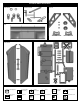
ULTRA LX2 ELECTRIC POWERED EXPLODED VIEW 30540 30686 36740 36741 36740 30361 36743 36742 30361 36742 36850 36740 30658 36700 36790 36740 40038 36700 40039 30380 30151 30102 30151 30655 30689 41010 30010 30082 B-B 30403 36020 30130 36861 36850 36690 40199 A-A 30657 30010 30403 34027 36170 30341 34053 36171 40528 30160 40527 40536 40520 36171 40528 30240 40527 30656 C-C 40550 21
30560 40642 30662 30662 30665-(14T) 30662 37410 36100 (86.
41010 30270 30649 30270 D-D 16015 34033 36861 30270 36850 40065 30403 36850 30351 30351 34027 A-A 30341 36082 40550 30010 30686 C-C 30130 30686 40102 34054 40199 36081 30656 30403 34063 40102 30082 30010 36171 34055 36171 FRONT SHOCK ASSEMBLY B-B A-A 30773 30779 40058 30769 30769 41015 40054 30761 41008 40643 41003 30901 30901 41005 30121 40113 30751 41013 30403 30121 41012 41011 41008 40060 41006 30769 30120 41007 40643 REAR SHOCK ASSMEBLY B-B D-D B-B C
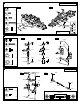
SETTING GUIDE FRONT CAMBER ANGLE SETTING REAR CAMBER ANGLE SETTING Positive Negative + Positive Negative - - + + - - Turnbuckle + Turnbuckle Place the model car on flat surface. Raise the chassis to its maximum clearance before the wheels leave the ground. Adjust the length of the front and rear upper arms so that the wheels are vertical to the ground. Adjust the camber angle by turning the turnbuckle rod on the upper arms clockwise or counter-clockwise.
OFNA 16015 30010 30082 30102 30110 30120 30121 30130 30160 30201 30240 30270 30341 30351 30361 30380 30401 30403 30411 30620 30630 30649 30653 30656 30657 30658 30661 30662 30663 30665 30673 30674 30675 30676 30686 30751 30761 30769 30773 30776 30777 30779 30780 30901 30911 31143 31159 34014 34027 34054 34055 34063 34302 ULTRA LX2e PARTS LIST DESCRIPTIONS HI FORCE WING, 1/8 WHITE GEARBOX, ULTRA SERIES CAP JOINTS, 6mm, 2 PCS. BODY MOUNT POSTS, 2 PCS.
34302 ULTRA LX2e OPTION PARTS OFNA 10231 10232 10233 10234 10235 10236 10237 10238 10239 10772 10773 10774 10775 10776 10777 10994 16016 16017 16018 16019 30664 30666 30667 30668 30774 33991 33995 33996 33997 41014 41016 41017 41018 41020 41021 41023 41024 41025 41026 41028 41029 41030 41116 40570 86057 86058 DESCRIPTIONS DIFF OIL,SILICON 1000 WT DIFF OIL,SILICON 3000 WT DIFF OIL,SILICON 5000 WT DIFF OIL,SILICON 7000 WT DIFF OIL,SILICON 10,000 WT DIFF OIL,SILICON 30,000 WT DIFF OIL,SILICON 50,000 WT DIF
OWNER’S REGISTRATION CARD OFNA Racing congratulates you on your purchase of our fine OFNA Product. With proper maintenance and handling this kit will provide many hours of enjoyment. The registration card should be filled out and mailed to OFNA Racing within 10 days of purchase date.