99 Washington Street Melrose, MA 02176 Phone 781-665-1400 Toll Free 1-800-517-8431 Visit us at www.TestEquipmentDepot.
ii
Compliance to the following standards is indicated by the corresponding marking on the product. Marking Standard This product conforms to the EMC Directive 89/336/EEC, the Low Voltage Directive 73/23/EEC and the Non-automatic Weighing Instruments Directive 90/384/EEC. The complete Declaration of Conformity is available from Ohaus Corporation. AS/NZS4251.1, AS/NZS4252.
Disposal In conformance with the European Directive 2002/96/EC on Waste Electrical and Electronic Equipment (WEEE) this device may not be disposed of in domestic waste. This also applies to countries outside the EU, per their specific requirements. Please dispose of this product in accordance with local regulations at the collecting point specified for electrical and electronic equipment.
3000 Series Indicators EN-1 TABLE OF CONTENTS 1. 1.1 1.2 1.3 INTRODUCTION..........................................................................................................................................EN-4 Safety Precautions .....................................................................................................................................EN-4 Overview of Parts and Controls .........................................................................................................
EN-2 3000 Series Indicators TABLE OF CONTENTS (Cont.) 3.5 Readout M enu .........................................................................................................................................EN-21 3.5.1 Re set ...........................................................................................................................................EN-21 3.5.2 F ilter ...........................................................................................................................
3000 Series Indicators EN-3 TABLE OF CONTENTS (Cont.) 3.10 Security Switch .......................................................................................................................................EN-28 4. OPERATION .............................................................................................................................................EN-28 4.1 Turning Indicator On/Off .........................................................................................................
EN-4 1. 3000 Series Indicators INTRODUCTION This manual contains installation, operation and maintenance instructions for the T31P and T31XW Indicators. Please read this manual completely before installation and operation. 1.1 Safety Precautions For safe and dependable operation of this equipment, please comply with the following safety precautions: • Verify that the input voltage range printed on the data label matches the local AC power to be used.
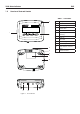
3000 Series Indicators 1.2 EN-5 Overview of Parts and Controls TABLE 1-1. T31P PARTS. 2 1 3 Item Description 1 Data Label 2 Front Housing 3 Control Panel 4 Security Screw 5 Key Hole (4) for wall mounting 6 Screw (4) 7 Data Label 8 Rear Housing 9 Power Receptacle 10 Strain Relief for Load Cell Cable 11 RS232 Connector 4 5 6 7 8 9 10 Figure 1-1. T31P Indicator.
EN-6 1.2 3000 Series Indicators Overview of Parts and Controls (Cont.) 1 2 3 4 5 6 7 8 9 10 Figure 1-2. T31XW Indicator. 11 TABLE 1-2. T31XW PARTS.
3000 Series Indicators 1.2 EN-7 Overview of Parts and Controls (Cont.) J4 OFF ON 9 J5 W1 1 2 3 4 W2 5 6 J7 J6 7 8 Figure 1-3. Main PC Board. TABLE 1-3. MAIN PC BOARD.
EN-8 1.2 3000 Series Indicators Overview of Parts and Controls (Cont.) 1 14 2 3 4 13 12 11 10 9 8 7 6 Figure 1-4. Controls and Indicators. TABLE 1-4. CONTROL PANEL. No.
3000 Series Indicators 1.3 EN-9 Control Functions TABLE 1-5. CONTROL FUNCTIONS. Button Primary Function (Short Press) ON/ZERO If Indicator is On, sets zero. PRINT FUNCTION Sends the current value Initiates an application to the COM port if mode. AUTOPRINT is set to Off. TARE Performs a tare operation. Secondary Function (Long Press) Off Turns the Indicator on or off. Units Changes the weighing Unit. Menu Enter the User menu. Mode Allows changing the application mode.
EN-10 3000 Series Indicators 2. INSTALLATION 2.1 Unpacking Unpack the following items: • T31P or T31XW Indicator • AC Adapter (T31P only) • Mounting Bracket (supplied with T31XW only) • Knobs (2) (supplied with T31XW only) • Capacity Label Sheet • Instruction Manual CD • Warranty Card • LFT sealing Kit 2.2 External Connections 2.2.1 RS232 interface Cable to T31P Connect the optional RS232 cable to the RS232 connector Figure 1-1, item 13).
3000 Series Indicators EN-11 2.2.4 Battery Power (T31P Only) The indicator can be operated on the internal rechargeable battery when AC power is not available. The indicator will automatically switch to battery operation if there is a power failure or the power cord is removed. Note: Before using the indicator for the first time, the internal rechargeable battery should be fully charged for up to 12 hours. The indicator can be operated during the charging process.
EN-12 3000 Series Indicators T31P Remove the four Phillips head screws from the rear housing. Open the housing being careful not to disturb the internal connections. Once all connections are made, reattach the front housing. T31XW Remove the four hex head screws from the rear housing. Open the housing by carefully pulling the top of the front housing forward. Once all connections are made, reattach the front housing. The screws should be tightened fully to maintain a watertight seal. 2.3.
3000 Series Indicators 2.4 EN-13 T31P Rear Cover Orientation The T31P is delivered in the wall mount orientation with the connections exiting below the display. The rear housing may be reversed so the connections exit above the display when the T31P is placed horizontally on a bench. See Figure 2-4. To reverse the rear housing, remove the four Phillips head screws, carefully rotate the housing 180°, and reinstall the screws. CAUTION: Take care not to pinch any internal Figure 2-3.
EN-14 3000 Series Indicators 3 SETTINGS 3.1 Menu Structure TABLE 3-1. MENU STRUCTURE. 6(783 &$/ <(6 5(6(7 63$1 5($'287 2)) /)7 <(6 5(6(7 12 5(6(7 12 /2: 0(' +,*+ $9* /(9(/ 21 02'( &2817 <(6 5(6(7 12 .,/2*5$06 21 3281'6 NJ OE 1 (1' )6 &$3$&,7< (;3$1' 02'( 6(/(&7 &$3 $1' 81,7 *5$' %$&. /,*+7 6(/(&7 *5$' < 6+87 2)) J .
3000 Series Indicators 3.2 EN-15 Menu Navigation TO ENTER THE MENU MODE Press and hold the Menu button until MENU appears on the display. The first upper level menu appears on the display. Summary of button navigation functions in menu mode: --Yes Allows entry into the displayed menu. - Accepts the displayed setting and advances to the next menu item. --No Skips by the displayed menu. - Rejects the displayed setting or menu item and advances to the next available item.
EN-16 3000 Series Indicators 3.3.1 Span Calibration Span Calibration uses two points to adjust the scale. The first point is the zero value where there is no weight on the scale. The second point is the Span value where a calibration mass is placed on the scale. When SPAN is displayed, press the Yes button to access the Span Calibration menu item. The display flashes 0. With no weight on the scale, press the Yes button to establish the zero point.
3000 Series Indicators 3.3.3 Geographical Adjustment Factor The Geographcial Adjustment Factor (GEO) is used to compensate for variations in gravity. Note: Changing the GEO Factor alters the calibration. The GEO value was set at the factory and should only be changed by an authorized manufacturer’s representative or certified verirication personnel. Refer to table 3-2 to determine the GEO factor that corresponds to your location. 3.3.4 End C alibration Advance to the next menu.
EN-18 3000 Series Indicators TABLE 3-2. GEOGRAPHICAL ADJUSTMENT VALUES Geographical latitude away from the equator, (North or South) in degrees and minutes.
3000 Series Indicators 3.4 EN-19 Setup Menu When the Indicator is used for the first time, enter this menu to set the Capacity and Graduation. Reset Legal orf rTade Cal Uni t Capacity Graduation Power On Unit Zero Range End Se tup No, Yes Off, On kg, lb 5…20000 0.001…20 g, kg, lb, oz, lb:oz, Auto 0%, 2%, 100% Exit SETUP menu 3.4.1 Reset Reset the Setup menu to the factory defaults. No = not re set. Yes = re set.
EN-20 3000 Series Indicators TABLE 3-3. SETUP AND CALIBRATION VALUES Capacity Graduation size with LFT OFF Graduation size with LFT ON Span calibration points Linearity calibration points 5 0.001, 0.002, 0.005 5 2, 5 0.002, 0.005, 0.01 5, 10 5, 10 0.005, 0.01 0.005, 0.01, 0.02 5, 10, 15 5, 10, 15, 20 5, 15 10, 20 0.005, 0.01, 0.02 0.005, 0.01, 0.02 0.01, 0.02 0.01, 0.02, 0.05 0.01, 0.02, 0.05 0.02, 0.05 0.02, 0.05, 0.
3000 Series Indicators EN-21 3.4.5 Graduation Set the scale readability. 0.001, 0.002, 0.005, 0.01, 0.02, 0.05, 0.1, 0.2, 0.5, 1, 2, 5, 10, 20. NOTE: Not all settings are available for each capacity. Refer to the Setup Table 3.3 for available settings. • • • 3.4.6 Power On Unit Set the unit that will be active at power on. oz, lb, g, kg, lb:oz or Auto (last unit in use when power was turned off.) 3.4.7 Zero Range Set the percentage of scale capacity that may be zeroed.
EN-22 3000 Series Indicators 3.5.2 Filter Set the amount of signal filtering. LO = less stability, faster stabilization time (<1 sec.) MEd = normal stability, stabilization time (<2 sec.) HI = greater stability, slower stabilization time (<3 sec.) 3.5.3 Auto-Zero T racking Set the automatic zero tracking functionality. OFF = di sabled. 0.5 d = the display will maintain zero until a drift of 0.5 divisions per second has been exceeded.
3000 Series Indicators 3.6 EN-23 Mode Menu Enter this menu to activate the desired application modes. 3.6.1 Reset Set the Mode menu to the factory defaults. No = not re set. Yes = re set. NOTE: If the Legal for trade menu item is set ON, the settings are not reset. 3.6.2 Parts Counting Mode Set the status. OFF ON = Disabled = Enabled 3.6.3 End Mode Advance to the next menu.
EN-24 3.7 3000 Series Indicators Unit Menu Enter this menu to activate the desired units. Default settings are bold. Reset: Kilograms: Pounds: Grams: Ounces: Pounds:Ounces End Uni t No, Yes Off, On Off, On Off, On Off, On Off, On Exit UNIT menu 3.7.1 Reset Set the Unit menu to the factory defaults. Settings: NO = ont re set. YES = eset r If the Legal for Trade menu item is set ON, the settings are not reset. 3.7.2 Kilogram U nit Set the status. OFF ON kg = Di sabled = nEabled 3.7.
3000 Series Indicators EN-25 3.7.7 End Unit Advance to the next menu. 3.8 Print Menu Enter this menu to define printing parameters. Default settings are bold. Reset Baud Rate: 3.8.1 Reset Set the Print menu to factory defaults. NO = not re set. YES Parity: Stop Bi t Handshake: Stable Only Auto Pri nt = re set. NOTE: If the Legal for Trade menu item is set to ON, the following settings are not reset: Stable, Auto Print Content Exit PRINT menu 3.8.2 Baud Set the Baud rate.
EN-26 3.8.4 Stop Bit Set the number of stop bits. 1 = 1 top s bi t. 2 = 2 top s bi ts. 3.8.5 Handshake Set the flow control method. NONE = no hands haking. ON-OFF = XON/XOFF software handshaking. 3.8.6 Print Stable Data Only Set the print critera. OFF = values are printed immediately. ON = values are only printed when the stability criteria are met. 3.8.7 Auto P rint Set the automatic printing functionality. OFF = di sabled. ON.StAb = printing occurs each time the stability criteria are met.
3000 Series Indicators 3.9 EN-27 Menu Lock Menu Enter this menu. Default settings are bold. 3.9.1 Reset Set the menu Lock menu to factory defaults. NO = not re set. YES = reset. NOTE: Settings for LFT controlled menu items are not reset. 3.9.2 Lock Calibration Set the status. OFF ON = Calibration menu is not locked. = Calibration menu is locked and hidden. 3.9.3 Lock Setup Set the status. OFF ON = Setup menu is not locked. = Setup menu is locked and hidden. 3.9.4 Lock Readout Set the status.
EN-28 3000 Series Indicators 3.9.7 Lock Print Set the status. OFF ON = Print menu is not locked. = Pri nt me nu si ocked. l 3.9.8 End L ock Advance to the next menu. 3.10 Security Switch A security switch is located on the Main PCB board. When the switch is set to the on position, user menu settings that were locked in the Menu Lock can not be changed. Open the housing as explained in Section 2.3.1. Set the position of security switch to ON as shown in Figure 1-3. 4 OPERATION 4.
3000 Series Indicators 4.4 EN-29 Changing Units of Measure Press and hold the PRINT Units button until the desired measuring unit appears. Only measuring units enabled in the Unit Menu will be displayed (refer to Section 3.7). 4.5 Printing Data Printing the displayed data to a printer or sending the data to a computer requires that the communication parameters in the Print Menu are set (refer to Section 3.8).
EN-30 Recalling a Stored APW Press the No button to recall the existing APW. Press the FUNCTION Mode button to temporarily display the APW value. Establishing the Average Piece Weight (APW) The display shows Put10 Pcs. Establishing a New APW Press the No button to increment the sample size. Choices are 5, 10, 20, 50, 100 and 200. To establish the APW, place the specified quantity of samples on the scale and press the Yes button to capture the weight.
3000 Series Indicators 5 EN-31 SERIAL COMMUNICATION The T31P and T31XW Indicators include an RS232 serial communication interface. The setup of RS232 operating parameters are more fully explained in Section 3.8. The physical hardware connection is explained in in Section 2.2. The interface enables display data to be sent to a computer or printer. A computer can be used to control some functions of the indicator using the commands listed in Table 5-1. 5.
EN-32 5.2 3000 Series Indicators Output Format The default serial output format is shown below. Field: Length: Polarity Space Weight Space Unit Stability 1 1 7 1 5 1 Legend 3 CR LF 1 1 Definitions: Polarity, “-” sign if negative, blank if positive. Weight, up to 6 numbers and 1 decimal, right justified, leading zero blanking. Units, pu ot 5 haracters. c Stability, “?” character is printed if not stable, blank if stable.
3000 Series Indicators 6. LEGAL FOR TRADE 6.1 Settings EN-33 Enter the menu to verify the settings and perform a calibration as explained in Section 3. Set the LFT menu to ON. Exit the Setup menu and power off the indicator. Open the housing as explained in Section 2.3.1. Set the position of the security switch to ON as shown in Figure 1-3, (item 9). Close the housing.
EN-34 7 3000 Series Indicators MAINTENANCE CAUTION: DISCONNECT THE UNIT FROM THE POWER SUPPLY BEFORE CLEANING. 7.1 Model T31P Cleaning • The housing may be cleaned with a cloth dampened with a mild detergent if necessary. • Do not use solvents, chemicals, alcohol, ammonia or abrasives to clean the housing or control panel. 7.2 Model T31XW Cleaning • Use approved cleaning solutions for the stainless-steel Indicator housing and rinse with water. Dry thoroughly.
3000 Series Indicators EN-35 TABLE 7-1. ROUBLESHOOTING T (Cont.). SYMPTOM PROBABLE CAUSE(s) REMEDY Err 9.0 Internal fault Service required. Err 9.5 Calibration data not present. Calibrate scale. Err 53 EEPROM data incorrect. Service required. CAL E Calibration Error. Calibration value outside allowable limits. Repeat calibration using correct calibration weights. LOW.rEF The average piece weight of the parts is small (warning).
EN-36 3000 Series Indicators 8. TECHNICAL DATA 8.1 Specifications Materials T31XW Housing: stainless steel T31P Housing: ABS plastic Keypad: polyester Feet: Rubber Display Window: Polycarbonate Ambient conditions The technical data is valid under the following ambient conditions: Ambient temperature: -10°C to 40°C / 14°F to104°F Relative humidity: Maximum relative humidity 80% for temperatures up to 31°C decreasing linearly to 50% relative humi dity at 4 0°C.
3000 Series Indicators 8.2 EN-37 Accessories TABLE 8-2. ACCESSORIES.
EN-38 8.3 3000 Series Indicators Drawings and Dimensions Figure 8-1. T31P Indicator Overall Dimensions. Figure 8-2. T31XW Indicator Overall Dimensions with Mounting Bracket.
LIMITED WARRANTY Ohaus products are warranted against defects in materials and workmanship from the date of delivery through the duration of the warranty period. During the warranty period Ohaus will repair, or, at its option, replace any component(s) that proves to be defective at No charge, provided that the product is returned, freight prepaid, to Ohaus.
*80251064* P/N 80251064 B © Ohaus Corporation 2008, all rights reserved. Printed in China Test Equipment Depot - 800.517.8431 - 99 Washington Street Melrose, MA 02176 - TestEquipmentDepot.