OKIPAGE 4 /4 LED Page Printer Maintenance Manual OEL/INT Approval All specifications are subject to change without notice.
HP, LaserJet and PCL5e are trademarks of Hewlett-Packard Co.
PREFACE This Maintenance Manual describes the field maintenance methods for LED Page Printers. This manual is written for use by service persons. Please note that you should refer to the Printer Handbook for the handling and operating methods of the equipment.
CONTENTS 1. CONFIGURATION ..................................................................................... 1.1 System Configuration ........................................................................ 1.2. Printer Configuration .......................................................................... 1.3 Option ................................................................................................. 1.4 Specification .........................................................................
4. ADJUSTMENT ........................................................................................... 4 - 1 4.1 Adjustment Types and Functions ...................................................... 4 - 1 4.1.1 4.1.2 Printer Driver ........................................................................................... 4 - 1 Engine Maintenance Utility ...................................................................... 4 - 3 4.2 Adjustment When Replacing a Part ....................................
1.
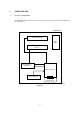
1. CONFIGURATION 1.1 System Configuration The OKIPAGE 4w Plus/4m consists of a control block, a power supply unit, and an engine block. (See Figure 1-1.
1.2 Printer Configuration The printer unit consists of the following five hardware components: • • • • • Electro-Photographic Processor Paper Feeder Main Control Board High-Voltage Power Supply Board Power Supply Unit Figure 1-2 is the configuration of the printer unit.
1.
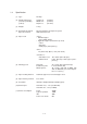
1.4 Specification (1) Type Desktop (2) Outside dimensions (excludes protruding portion) Height 5.9” Width 12.2” Depth 7.5” (3) Weight 3.8 kg (4) Development method Exposure method Dry non-magnetic development system LED stationary head (5) Paper used • Standard paper – Xerox 4200 (20 lbs) • Application paper (manual face-up feed) – Label – Envelope – OHP paper (Transparency) (150 mm) (310 mm) (191 mm) 14" (355.6 mm) (Max.) x 8.5" (215.
(12) Temperature and humidity Humidity Temperature During operation 10 to 32 ˚C 20 to 80% RH (relative humidity) In storage –10 to +43 ˚C 10 to 90% RH (relative humidity) No condensation is permissible. Caution: Temperature and humidity in storage are measured with the OKIPAGE 4w plus/4m being packed; they are valid for one year.
1.5 Safety Standards 1.5.1 Certification Label The safety certification label is affixed to the following location of the OKIPAGE 4w: OKI-INT 4w Plus 1.5.2 Warning Label Warning labels are affixed to the locations that may cause bodily injury. During maintenance, do work with enough care while following instructions on these warning labels.
2.
2. OPERATION DESCRIPTION The OKIPAGE 4w Plus/4m consists of a main control board, a high-voltage power supply board, a power supply unit, and an electro-photographic processor. The OKIPAGE 4w Plus/4m receives print data from a higher-level interface and sequentially stores it in memory. The OKIPAGE 4w Plus/4m decodes and edits the received data while storing print data from the interface in memory. It sequentially transfers the edited data to the LED head for each dot line.
2-2 5V OVL 5V Reset circuit TEMP TR-VSEN TR-ISEN Sensors Electromagnetic clutch Main motor LED head Parallel I/F EEPROM 10 MHz MSM65917 (nX-8 core) Driver A0 ~ A10 AD0 ~ AD7 A8 ~ A15 HEAT ON Parallel I/F Manual feed sensor Paper sensor Outlet sensor Toner sensor Cover open switch Driver Driver Switching power supply +24 V +5 V 0VL 0VP AC output ON/OFF High voltage power supply LED LS07 CN Driver TEMP High-voltage power I/
Parallel I/F Mac I/F EEPROM 10 MHz 2-3 5V OVL 5V Reset circuit TEMP TR-VSEN TR-ISEN Sensors Electromagnetic clutch Main motor LED head Driver IC MSM65917 (nX-8 core) Driver A0 ~ A10 AD0 ~ AD7 A8 ~ A15 HEAT ON D-RAM (2 MByte) option (Option RAM-PCB) Parallel I/F Manual feed sensor Paper sensor Outlet sensor Toner sensor Cover open switch Driver Driver Switching power supply +24 V +5 V 0VL 0VP AC output ON/OFF High voltage po
2.1 Main Control Board The main control board consists of a one-chip CPU, a program ROM, a DRAM, an EEPROM, a host interface circuit, and a mechanism driving circuit. The mechanism driving circuit consists of a LED head, a main motor, and an electromagnetic clutch. (1) One-chip CPU The one-chip CPU is a custom CPU (8-bit internal bus, 8-bit external bus, 10-MHz clock) incorporating mask ROM and CPU peripheral devices. This CPU has the functions listed in the table below.
2.2 Power Supply Unit The power supply unit supplies +5 V and +24 V to the main control board according to 230 VAC /120 VAC. Output voltage Application +5 V Used to generate a logic circuit and a high voltage. +24 V Used to drive the motor and electromagnetic clutch. The power supply unit also contains a heater drive circuit. 2.
(2) Sensors The high-voltage power supply board consists of the high-voltage power supply circuit that supplies power to the electro-photographic processor system and the photosensor that detects a paper feeding system and toners. Figure 2-2 shows the sensor layout drawing.
2.4 Electro-Photographic Processor The electro-photographic processor prints out the image data to be sent from the main control board on sheets of paper. Figure 2-3 shows the layout drawing of the electro-photographic processor. (1) Image drum unit The image drum unit makes a toner adhere to the formed electrostatic latent image with static electricity. This electrostatic latent image is formed by the lights irradiated from LED heads.
2-8 Manual feed sensor Manual printing Feed roller ON OFF 10 10 Tray printing 23.18 OFF 12.72 17.23 32.00 Cleaning roller (ø 9.000) 6.85 64.60 Hopping roller 20.32 26.50 Transfer roller (ø 15.000) Outlet sensor ON 10 Figure 2-3 Layout Drawing of Electro-Photographic Processor Paper sensor Developing roller (ø 14.000) Drum roller (ø 16.000) LED head 6.77 Charge roller (ø 9.000) Heat roller (ø 19.
(3) Pulse motor (Main) This pulse motor of 48 steps/rotation is two-phase excited by the signal from the main control board; it performs feeding control by switching normal rotation to reverse rotation or vice versa and turning on/off the electromagnetic clutch. The relationship between the main motor, electromagnetic clutch, resist gear, drum gear, hopping roller is shown in the table below and on the subsequent pages.
2 - 10 Manual feed sensor Manual printing Transfer roller Cleaning roller CH roller Heat roller Outlet sensor Exit roller Figure 2-4 Schematic Drawing of OKIPAGE4w Plus/4m Paper Feeding 2 Reverse rotation of pulse motor (main): Drum roller, transfer roller, cleaning roller, CH roller, developing roller, heat roller, exit roller, feed roller, hopping roller rotation Hopping operation from the tray, however, is performed when the electromagnetic clutch is turned on.
2.5 Electro-Photographic Process (1) Electro-photographic process The electro-photographic process is outlined below. 1 Charging The surface of the OPC drum is charged negatively and uniformly by applying the DC voltage to the CH roller. 2 Exposure Light emitted from the LED head irradiates the negatively charged surface of the OPC drum. The surface potential of the irradiated surface attenuates to form the electrostatic latent image corresponding to the image signal.
2 - 12 Paper ejection Fusing Fusing Paper feeding Heat roller Outlet sensor Paper eject roller Paper delivery Back-up roller Power supply Transfer Cleaning Charging Transfer roller Transfer Exposure LED head Development Paper sensor Development Developing roller Power supply Paper feed Feed roller Figure 2-5 Flow for Electro-Photographic Process Cleaning Cleaning roller Power supply Charge roller Power supply Control signal Paper hopping Manual feed sensor Manual feed secti
2.5.1 Explanation of Each Process Operation (1) Hopping As shown in the figure below, the clutch for hopping is turned on/off according to current ON/ OFF to a coil. When the clutch is OFF Spring for resetting Hopping gear Clutch plate Coil Magnetic substance plate Pin Hopping shaft Hopping roller Engagement section When the clutch is ON Hopping gear Clutch plate When the clutch is on, the hopping gear engages with the clutch plate to rotate the hopping roller.
(2) Printing and warm-up At warm-up Triple gear Transfer gear Resist gear Idle gear Planetary gear a" a' a Hopping gear Gear A Pulse motor (main) Rotate the pulse motor (main) in the a direction. The planetary gear rotates in the a’ direction, dislocating its position in the a” direction. This causes the planetary gear to be separated from gear A. The hopping gear will not rotate. The triple gear and transfer gear rotate via the idle gear to drive the EP unit.
(3) Charging Charging is performed by applying DC voltage to the charge roller that is in contact with the surface of the OPC drum. Highvoltage power supply Charge roller OPC drum (4) Exposure Light emitted from the LED head irradiates the negatively charged surface of the OPC drum. The surface potential of the irradiated surface attenuates to form the electrostatic latent image corresponding to the image signal.
(5) Development The electrostatic latent image on the surface of the OPC drum is changed to a visible toner image by applying a toner to it. Development is performed in the contact part between the OPC drum and developing roller. 1 The sponge roller negatively charges a toner and applies it to the developing roller. Developing blade Charge roller Sponge roller Developing roller OPC drum 2 The toner applied to the developing roller is thin-coated by the developing blade.
(6) Transfer The transfer roller is composed of conductive sponge material. This roller is set so that the surface of the OPC drum and sheets of paper will adhere closely. A sheet of paper is placed on the surface of the OPC drum and the positive charge opposite to the negative charge of a toner is applied from the reverse side by the transfer roller.
(7) Fusing The transferred unfused toner image is fused to a sheet of paper because heat and pressure are applied when it passes between the heat roller and back-up roller. The Teflon-coated heat roller contains a 400 W heater (Halogen lamp) that heats the heat roller. The thermistor on the surface of the heat roller keeps the temperature of the heat roller constant. A thermostat is also installed for safety. If temperature rises abnormally, this thermostat opens to suspend voltage supply to the heater.
2.6 Paper Jam Detection The OKIPAGE 4w Plus/4m monitors the paper status when the power supply is on and during printing. In the following cases, the OKIPAGE 4w Plus/4m interrupts the printing process as a paper jam. Printing can be recovered by opening the cover, removing the jammed paper, and closing the cover. Error Paper inlet jam Cause of Error • Only the manual feed sensor detects "Paper exists" when the power supply is on.
Pulse motor (main) Normal rotation OFF Reverse rotation Electromagnetic clutch OFF ON Manual feed sensor OFF ON OFF ON Paper sensor Outlet sensor OFF ON Warm-up Paper feed Printing Operation mode Timing Chart for Paper Feed (Tray Feed) 2 - 20
Paper Feed Check List 2.7 Toner Low Detection • Hardware configuration of toner sensor The figure below shows the hardware configuration of the toner sensor. Image drum unit Agitation bar (iron) Magnet Toner sensor lever Photointerrupter Hardware Configuration of Toner Sensor • Toner detection method (1) Toner sensor monitoring conditions are shown in the figure below. Toner sensor Magnet draw-in t1 T Caution: The toner sensor is not monitored when the drum is inactive.
(2) The basic rotation cycle of the toner sensor is as follows: T time Basic rotation cycle of toner sensor Toner low time t1 > 1.2 sec. 1.2 sec. > t1 > 0.28 sec. Toner full time 2.8 4.9 sec. Cover Open Opening the stacker cover turns off the microswitch on the high-voltage power supply board to suspend +5 V supply to the high voltage power supply. This results in the stop of all high-voltage outputs.
3.
3. PARTS REPLACEMENT This chapter explains how to replace parts, assemblies, and units in the field. The replacement procedures to be explained here include dismounting, not mounting. When mounting parts, assemblies, and units, reverse the dismounting steps. 3.1 Precautions for Parts Replacement (1) Be sure to dismount the AC cord and interface cable before replacing parts. (a) Be sure to dismount the AC cord in the following procedures: i) ii) iii) Turn off the POWER switch of the printer (“0“).
[Maintenance Tools] Table 3-1 lists the maintenance tools necessary for parts replacement. Table 3-1 Maintenance Tools No. Maintenance Tools Q'ty Use 1 No. 1-100 Philips screwdriver 1 2~2.5 mm screw 2 No. 2-100 Philips screwdriver 1 3~5 mm screw 3 No. 3-100 Philips screwdriver 1 4 No. 5-200 screwdriver 1 5 Digital multimeter (tester) 1 6 Pliers 1 7 Handy cleaner 1 Remarks [Maintenance Utility] Table 3-2 Maintenance Utility No.
3.2 Parts Layout This section explains the layout of main parts.
[Base Frame Unit] Flat cable assy LED head Head spring Top cover assy Pressure roller (B) (Back up roller) Paper guide (R) Heat assy Transfer roller Paper guide (L) Resistration roller Idle gear heat Hopper spring Paper holder Drive shaft E (eject) Tension plate Slide plate M Stopper spring Hopping shaft Magnet H assy (hopping shaft) Roller holder Hopping roller High-voltage power supply board Pulse motor (main) Toner cartridge unit Power sensor E EP unit Sheet guide Figure 3-2 3-4
[Base Plate Unit] Power supply unit Main control board Base plate assy Figure 3-3 3-5
3.3 Replacing Parts This section explains how to replace parts and assemblies. 3.3.1 Hopper Plate (1) Remove two claws and dismount hopper plate 1.
3.3.2 LED Head and Head Spring (1) Open top cover assy 1. (2) Dismount the left clamp and LED head 2. Then, dismount flat cable assy 3. (3) Dismount two head springs 4.
3.3.3 Transfer Roller (1) Open top cover assy 1 and dismount EP unit 2. (2) Remove the right claw. Then, dismount transfer roller 3, two resist bearings 4, and gear T5.
3.3.4 Upper Cover Assy (1) Turn off the power switch and unplug the AC cord from the AC socket. (2) Disconnect interface cable 1. (3) Open top cover assy 2 and dismount EP unit 3. (4) Move paper guide (L) 4 and paper guide (R) 5 on the rear of the printer to the center. (5) Remove two front claws of upper cover assy 6 and two rear screws A and lift upper cover assy 6. (6) Dismount spur gear (A) 7, guide slide (L) 8, and guide slide (R) 9. (7) Dismount lamp 0.
3.3.5 High-Voltage Power Supply Board (1) Dismount upper cover assy. (See Section 3.3.4.) (2) Remove three screws 1 and draw out high-voltage power supply board 2. (3) Disconnect all the cables 3 from high-voltage power supply board 2 and dismount highvoltage power supply board 2. Caution: Note the following when assembling the high-voltage power supply board: • Mount the high-voltage power supply board with top cover assy removed or open.
3.3.6 Top Cover Assy and Flat Cable Assy (1) Dismount the upper cover assy. (See Section 3.3.4.) (2) Dismount the LED head. (See Section 3.3.2.) (3) Press the left clamp outward and dismount the engagement and top cover assy 1. (Tension spring 2 also comes off at the same time.) (4) Disconnect connector CN6 and dismount flat cable assy 3.
3.3.7 Paper Holder (1) Dismount the upper cover assy. (See Section 3.3.4.) (2) Dismount paper holder 1. (3) Unlock and dismount paper guide (L) 2 and paper guide (R) 3. (4) Remove the claw and dismount hopper spring 4. (5) Remove the claw and dismount stopper spring 5.
3.3.8 Side Plate M and Idle Gear Perform parts replacement while making the base frame assy stand so that side plate M will face upward. (1) Dismount the upper cover assy. (See Section 3.3.4.) (2) Remove two screws 1 and two claws, then dismount plate side M2. (3) Dismount earth plate 3, two idle gears P4, idle gear M5, idle gear 3R6, idle gear 2R7, and idle gear heat 8.
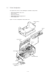
3.3.9 Heat Assy This section explains how to dismount the heat assy and parts in the assy. (1) Dismount the upper cover assy. (See Section 3.3.4.) (2) Dismount the high-voltage power supply board. (See Section 3.3.5.) (3) Remove two screws 1, disconnect connector 2, and dismount heat assy 3. (4) Dismount heat separator D. (5) Remove screw 4 and dismount terminal plate 6. (Handle heat assy 3 carefully because Halogen lamp 7 comes off.
1 1 3 2 3 - 15
7 C Voltage display side 8 8 9 5 A 0 6 4 3 - 16 B
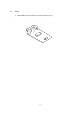
3.3.10 Drive Shaft E (Eject) and Eject Roller (1) Dismount the upper cover assy. (See Section 3.3.4.) (2) Dismount top cover assy. (See Section 3.3.6.) (3) Remove two screws 1 from heat assy (Section 3.3.9), lift the heat assy, and dismount idle gear E (A) 2 and idle gear E (B) 3. (4) Unlock and dismount drive shaft E (Eject) 4. (5) Dismount two eject rollers 5.
3.3.11 Pressure Roller B (Back Up Roller) (1) Dismount the upper cover assy. (See Section 3.3.4.) (2) Dismount the high-voltage power supply board. (See Section 3.3.5.) (3) Dismount the heat assy. (See Section 3.3.9.) (4) Dismount the engagement with the left ground, then pressure roller B1. (Two bearing BUs 2 and two bias springs 3 also come off at the same time.
3.3.12 Separator Guide (1) Dismount the upper cover assy. (See Section 3.3.4.) (2) Dismount the high-voltage power supply board. (See Section 3.3.5.) (3) Remove four screws 1. (4) Dismount inlet 2 from base frame 3. Insert a screwdriver into the hole on the side of base frame 3, remove the inlet claw from base frame 8, and dismount inlet 2. (5) Disconnect three cables 4 and connector A and dismount base frame 3. Then, remove screw 0 and disconnect FG cable B.
1 Screw driver 1 6 8 3 7 9 5 2 4 B 1 4 0 (–) Screw driver A Clamp lever 1 3 - 20
3.3.13 Pulse Motor (Main) (1) Dismount the upper cover assy. (See Section 3.3.4.) (2) Dismount the high-voltage power supply board. (See Section 3.3.5.) (3) Dismount side plate M. (See Section 3.3.8.) (4) Dismount the base frame. (See Section 3.3.12.) (5) Remove two screws 1 and dismount pulse motor (main) 2.
3.3.14 Hopping Shaft Assy (1) Dismount the upper cover assy. (See Section 3.3.4.) (2) Dismount the high-voltage power supply board. (See Section 3.3.5.) (3) Dismount the base frame. (See Section 3.3.12.) (4) Dismount the paper holder assy. (See Section 3.3.7.) (5) Dismount the sheet guide. (See Section 3.3.12.) (6) Dismount side plate M. (See Section 3.3.8.) (7) Raise up roller holder 3, slide hopping shaft assy 1, and dismount roller holder 3 and hopping roller 4.
3.3.15 Resist Roller (1) Dismount the upper cover assy. (See Section 3.3.4.) (2) Dismount Idle gear R 3 and Gear R 4. (3) Move resist roller 1 to the right and dismount it by lifting. (Two resist bearings 2 also come off at the same time. Take care not to lose them.
3.3.16 Paper Sensor E, Paper Sensor Exit and Toner Sensor Assy (1) Dismount the upper cover assy. (See Section 3.3.4.) (2) Dismount the high-voltage power supply board. (See Section 3.3.5.) (3) Dismount the base frame. (See Section 3.3.12.) (4) Dismount the paper holder assy. (See Section 3.3.7.) (5) Dismount the sheet guide. (See Section 3.3.12.) (6) Dismount the heat assy. (See Section 3.3.9.) (7) Dismount drive shaft E. (See Section 3.3.10.) (8) Dismount paper sensor E1. (9) Dismount paper sensor exit 2.
3.3.17 Base Plate (1) Dismount the upper cover assy. (See Section 3.3.4.) (2) Dismount the base frame. (See Section 3.3.12.) (3) Remove two screws 1, disconnect connector 2, and dismount power supply unit 3. (4) Dismount insulation sheet 4. (5) Remove two screws 5 and dismount main control board 6 from base plate 7.
4.
4. ADJUSTMENT This chapter explains adjustment necessary when a part is replaced. This adjustment is made by changing the parameters values set in EEPROM on the main control board. The printer driver or maintenance utility can be used to change these values. Only servicemen and maintenance personnel can use the maintenance utility. This utility cannot be made public for printer end users. 4.1 Adjustment Types and Functions 4.1.
(For Macintosh) (1) Drum counter reset This function resets the life of the drum counter when the EP unit is replaced. Clicking the “Reset” button resets the life. (2) Charge roller cleaning This function cleans the charge roller of the EP unit; it is used when printing is unclear. For details on how to operate this function, refer to “User’s Manual.
4.1.2 Engine Maintenance Utility See Appendix D. 4.2 Adjustment When Replacing a Part The table below lists the parts that requires adjustment when they are replaced. Part to be Replaced 4.2.1 Adjustment LED head Set the LED head drive time. Set the LED head dot count. EP unit Reset the drum counter. (Refer to "User's Manual".) Main control board Upload or download EEPROM data.
4.2.2 Setting the LED Head Dot Count There are two types of LED head dot count. Use the following label to identify these types. Use “LED Head Width” in the engine menu table to set the LED head dot count. (See Figure 4-2.
4.2.3 Uploading and Downloading EEPROM Data When the main control board is replaced, EEPROM data must be reflected on a new main control board. Use “EEPROM Operations” in the option tab of the maintenance utility to reflect EEPROM data on the new main control board. (See Figure 4-4.) Reflect EEPROM data on the new main control board in the following procedures: (1) Check that the printer and PC are connected by the parallel I/F, then execute the maintenance utility.
5.
5. PERIODICAL MAINTENANCE 5.1 Periodical Replacement Parts Table 5-1 lists the part and unit to be replaced periodically. Table 5-1 Routine Replacement Parts Part Name Part to be Checked Simultaneously Replacement Time Toner cartridge When "Toner Low" is displayed. EP unit When "Change Drum" is displayed. LED head Remarks Consumables Consumables Caution: Also reset the drum counter when replacing the EP unit. 5.
(1) Set the LED head cleaner in the LED lens array, as shown in the figure below, and slide the cleaner left and right several time to clean the head. Caution: Do not press the LED head cleaner against the LED lens array.
6.
6. TROUBLESHOOTING PROCEDURES 6.1 Troubleshooting Tips (1) Check the basic check points written in the user’s manual. (2) Gather detailed failure information as much as possible from the customer. (3) Check the printer under the condition close to that under which the failure occurred. 6.
6.5 Troubleshooting If a trouble occurs in the OKIPAGE 4w Plus/4m, troubleshoot according to the following procedures: Trouble Trouble indicated by the message displayed on the status monitor. Troubleshoot according to "Status Monitor Message List" (See Section 6.5.1.) Image problem (or trouble not displayed on the status monitor) 6.5.1 Perform detailed troubleshooting according to the troubleshooting flow. (See Section 6.5.2.) Troubleshoot according to Section 6.5.3.
Table 6-1 Category Normal status Status Message Status Code Display Content Remedy 6-3 Warming Up 18 00 Warming-up status Normal operation Online (Ready) 00 10 Online (ready) status Normal operation Power Save Mode 00 20 Power save status Normal operation Toner Low 10 00 The toner amount of the toner cartridge is small. Normal operation Toner Sensor 10 01 The EP unit is not installed or the toner sensor is faulty. Replace the toner cartridge.
Table 6-1 (Cont'd) Category Status Message Status Code Display Content Remedy Paper Size Error 30 00 Paper of improper size was fed. 2.52" (64 mm) L 15.77" (400.56 mm) Check the paper. Also check whether more than one sheet of paper were fed simultaneously. To release the error display, open the cover, then close it. If this error occurs frequently, see Section 6.5.2 3. Paper jam Paper Input Jam 31 00 A paper jam occurred when sheets of paper were being supplied. Check the paper.
Table 6-1 (Cont'd) Category Category Device configuration error Status Status Message Message Status Status Code Display Display Content Content Remedy Remedy 6-5 EEPROM Check Error 60 40 An error occurred during EEPROM check. Replace the main control board. (When replacing the main control board, also adjust EEPROM data.) (See Section 4.2.4.) Option RAM Check Error 60 60 An error occurred during option RAM check. Check the connection of the Option RAM PC board.
6.5.2 Status Message Troubleshooting Some failures cannot be corrected according to the status message trouble list. Troubleshoot these failures according to the following troubleshooting flowcharts: 1. 2. Flowchart No. Item No. The OKIPAGE 4w Plus/4m malfunctions after the power supply has been turned on. 1 Jam error Paper input jam 2-1 Paper feed jam 2-2 Paper exit jam 2-3 3. Paper size error 3 4.
1 The OKIPAGE 4w Plus/4m malfunctions after the power supply has been turned on. • Turn the power supply off, then on again. • Is the LED lamp on? • No Is the AC cable connected correctly? • No Connect the AC cable correctly.
[JAM error] 2-1 Paper input jam • Does a paper input jam occur when the power supply is turned on? • Yes Is the jammed paper on paper sensor E? • Yes Remove the jammed paper. • No Is paper sensor E (manual feed/paper) operating normally? • No Replace paper sensor E (manual feed or paper). • Yes • No Replace the high-voltage power supply board.
• Yes • No • Yes Measure the resistance of the pulse motor (main). Is the resistance normal (about 12.6 Ω)? Replace the pulse motor (main). Replace the main control board.
[JAM error] 2-2 Paper feed jam • Does a paper feed jam occur when the power supply is turned on? • Yes Is the jammed paper on paper sensor E (paper/exit)? • Yes Remove the jammed paper. • No Is paper sensor E (exit/paper) operating normally? • No Replace paper sensor E (exit or paper). • Yes • No Replace the high-voltage power supply board. Has the paper arrived at paper sensor E (paper)? • No Is the feed roller rotating? • No Check the gear block.
Paper size error • Is the paper of the specified size being use? • No • Yes Use paper of the specified size. Is paper sensor E (paper) operating normally? • No • Yes Replace paper sensor E (paper) or clean the inlet sensor on the high-voltage power supply board. Is the paper sensor (exit) operating normally? • No • Yes Replace the paper sensor (exit) or clean the outlet sensor on the high-voltage power supply board. Replace the high-voltage power supply board.
4 Heat assy error • Turn the power supply off, then on again. • Does the Halogen lamp of the heat assy go on? • No Is the Halogen lamp or thermostat disconnected? • Yes Replace the heat assy, Halogen lamp, or thermostat. • No • Yes • No • Yes Replace the power supply unit. Are the CN2 connectors of the power supply unit and main control board connected correctly? Connect the CN2 connectors correctly. Replace the main control board.
6.5.3 Image Troubleshooting This section explains how to troubleshoot when an image problem is output as a result of the printing. Figure 6-3 is an example of image problem output. Symptom Flowchart No. An image is light or blurred entirely. (Figure 6-3, A ) 1 Dark background density (Figure 6-3, B ) 2 A blank paper is output.
1 An image is light or blurred entirely. • Is the toner low? (Is "Toner Low" being displayed?) • Yes • No Supply a toner. Is the specified paper being used? • No • Yes Use the specified paper. Is the lens of the LED head dirty? • Yes • No Clean the LED head. Is the LED head installed correctly? (Check the CN6 connector of the main control board.) • No Install the LED head correctly.
2 Dark background density • Has the OPC drum being exposed to external light? • Yes • No Set the OPC drum in the OKIPAGE 4w Plus/4m and wait for about 30 minutes. Is the heat roller of the heat assy dirty? • Yes • No Clean the heat roller. Is the terminal of the EP unit in correct contact with the contact plate? (See Figure 6-4 D and Figure 6-5 D .) • No • Yes Contact the terminal correctly. Replace the EP unit.
4 Vertical black belt/stripe • Replace the EP unit. • Has this error been recovered? • Yes End Caution: After replacing the EP unit, reset the drum counter. (Refer to "Replacing the Drum Cartridge" in "User's Manual".) • No Replace the LED head. • Has this error been recovered? • Yes End Caution: Set the LED head drive time when replacing the LED head. (See Section 4.2.1.) • No 5 Replace the main control board or high-voltage power supply board. Cyclic defect Cycle Remedy EP drum 1.98" (50.
6 A blank paper is output. • Is the contact plate of the transfer roller in correct contact with the high-voltage power supply board? • No • Yes Contact the contact plate of the transfer roller correctly. Replace the transfer roller. • Has this error been recovered? • Yes • No End Is the terminal of the EP unit in correct contact with the contact plate? (See Figure 6-4 A B C D E and Figure 6-5 A B C D E .) • No • Yes Contact the terminal of the EP unit correctly. Replace the EP unit.
7 Poor fusing • Is the specified paper being used? • No • Yes Use the specified paper. (xerox 4200 (20 lbs)) Is the bias spring normal? (Tension: 2.5 kg) • No • Yes Replace the bias spring. Are the heater connector of the heat assy and the CN1 connector of the power supply unit connected correctly. • No • Yes Connect the connectors correctly. Replace the heat assy. • Has this error been recovered? • Yes • No End Replace the main control board or high-voltage power supply board.
8 Vertical white belt/spripe • Is the lens of the LED head dirty? • Yes • No Clean the LED head. Is the contact plate of the transfer roller in correct contact with the high-voltage power supply board? (See Figure 6-5 E .) • No • Yes Contact the contact plate of the transfer roller correctly. Replace the transfer roller. • Has this error been recovered? • Yes • No End Is the LED head installed correctly? (Check the CN6 connector of the main control board.
Contents A: B: C: D: E: F: Toner Supply Roller Developing Roller Charge Roller Cleaning Roller Transfer Roller Heat Roller Figure 6-4 6 - 20
Contents A: B: C: D: E: Toner Supply Roller Developing Roller Charge Roller Cleaning Roller Ground (Drum) E Figure 6-5 6 - 21
7.
LED Head 1 2 3 4 5 6 7 8 9 10 11 12 13 14 0VP 0VP 5V 5V 0V HDDT0-P HDDT1-P HDCLK-P HDLD-P STB1-N STB2-N STB3-N STB4-N FG M CN4 (Parallel Interface) 36 Black Brown Yellow 29 CN9 (Not Used) 13 2 17 CN8 (Power Clutch) Main Control Board (HBMC-2 PCB) CN7 (Main Motor) Orange 12.
LED Head 1 2 3 4 5 6 7 8 9 10 11 12 13 14 0VP 0VP 5V 5V 0V HDDT0-P HDDT1-P HDCLK-P HDLD-P STB1-N STB2-N STB3-N STB4-N FG 36 19 14 13 2 18 M 1 1 2 3 4 5 6 7 8 9 10 11 12 13 14 15 16 17 18 19 20 21 22 23 24 25 26 27 28 29 30 31 32 33 34 35 36 CN4 (Parallel Interface) CN7 (Main Motor) Black Brown Yellow Orange 12.
7.2 PCB Layout 7.2.1 Main Control Board (HBMC-2 PCB) (OKIPAGE 4w Plus) SWI 1 2 Short Plug Plug Setting Content Remarks A External EPROM is valid. For a Chinese product and all maintenance parts. B Mask ROM in the CPU is valid. For all products except Chinese product.
7.2 PCB Layout 7.2.2 Main Control Board (HBMC-3 PCB) (OKIPAGE 4m) SWI 1 2 Short Plag Plag Setting Content A External EPROM is valid. B Mask ROM in the CPU is valid. Remarks SP1 DIP Switch SW1-1 SW1-2 Switch Setting UPPER SIDE* LOWER SIDE UPPER SIDE* LOWER SIDE Content AUTO I/F FIX I/F (By SW2-2) FIX PARALLEL I/F FIX MAC I/F *Default setting. Do not change.
7.2.
8.
8.
Table 8-1 Cover Assy Upper No. Part Name Part No.
f e d d Z [ c g Z \ Y T k W T U ] X V T b T R ^ S O M Q P L L J l I F a N G E H D C 7 1 B 8 o 4 5 2 3 i A 0 9 6 3 Figure 8-2 Base Frame Unit 8-3 K
Table 8-2 Base Frame Unit No. Part Name Part No.
No. 34 Part Name Part No.
2 1 3 5 4 Figure 8-3 Heat Assy 8-6
Table 8-3 Heat Assy No. Part Name Part No.
7 7 7 7 9 3 6 4 8 2 1 Figure 8-4 Base Plate Unit 8-8
Table 8-4 Base Plate Unit No. Part Name Part No.
APPENDIX
Appendix A LOCAL PRINTING (1) The following operation enables the OKIPAGE 4w Plus/4m to print data by itselt. With the cover open, turn on the AC switch and then close the cover. The following print patterns are printed.
Appendix B PARALLEL INTERFACE (1) Connector • Printer side : 36-pin receptacle Type: 57RE-40360-730B-D29A (Daiichi Denshi) or equivalent • Cable side : 36-pin plug Type: 57-30360 (Daiichi Denshi) or equivalent (2) Cable • Cable length : 6 feet (1.8 m) max. (A Shielded cable composed of twisted pair wires is recommended for noise prevention.
(3) Parallel I/F signals Pin No. Signal Name 1 DATA STROBE 2 DATA BIT - 1 3 DATA BIT - 2 4 DATA BIT - 3 5 DATA BIT - 4 6 DATA BIT - 5 7 DATA BIT - 6 8 DATA BIT - 7 9 DATA BIT - 8 Direction Function (Compatible Mode) → PR Parallel data sampling strobe ↔ PR Printer parallel input/output data 10 ACKNOWLEDGE ← PR Completion of input data reception 11 BUSY ← PR The OKIPAGE 4w is not ready to receive data.
(4) Signal level • LOW : 0 V to +0.8 V • HIGH : +2.4 V to 5.0 V (5) Interface circuit a) Receiving circuit R R = 3.3KΩ (1.0-KΩ STROBE) +5V b) Sending circuit 3.3KΩ (Open Collector) +5V (6) Timing charts a) Data receiving timing (compatible mode) PARALLEL DATA (DATA BITs 1 to 8) 0.5 µs min. 0.5 µs min. 0.5 µs min. DATA STROBE 0.5 µs min. 0 min. 0.5 µs max. BUSY 0 min. 0 min. ACKNOWLEDGE 0.5 µs to 10 µs 0 min. b) INPUT PRIME timing (when the INPUT PRIME signal is enabled) 50 ms min. INPUT.
&'.
AppendixC Macintosh INTERFACE (OKIPAGE 4m) 1) Connector • Printer side • Cable side : 8-pin mini DIN receptacle Type TCS7187-01-201 (made by HOSHIDEN) or equivalent : 8-pin mini DIN plug Type TCP7180-01-110 (made by HOSHIDEN) or equivalent 2) Cable Apple system peripheral-8 cable (M0197 LL / B : made by Apple) 3) Interface signal Pin No.
5) Connector Pin Arrangement 8 7 5 6 4 2 3 1 (As viewed from the cable side) C-2
Appendix D 1. MAINTENANCE UTILITY OUTLINE OF MAINTENANCE UTILITY The maintenance utility is an application program that operates on Microsoft Windows 3.1 or higher. The maintenance utility has the following functions: • • • • • 2.
4. DETAIL OF EACH FUNCTION 4.1 Engine Menu Setting Engine Menu Setting is used to set, display, and change the following menu items: (See Figure D-1.) (1) Print Position Used to adjust the print start position. (2) LED Head Marking No. Used to adjust the exposure time of the LED head. (3) LED Head Width Used to specify the LED head dot count. (4) LED Head Wire Used to specify whether the data wire of the LED head is 300-1W, one-wire (non-adjustment) type or 300-2W two-wire (adjustment) type.
(1) Drum Count Number of revolutions of mounted EP drum (2) Total Drum Count Total number of revolutions of EP drum after shipment (3) Page Count Total number of printed pages after shipment clicking the "Reset" button cleans each counter. (4) Reset All Used to clear all counters. 4.3 Printer Status Printer Status is used to display the printer status. (See Figure D-1.) 4.4 Test Print Test Print is used to check whether the printer can print data normally after the maintenance utility has terminated.
4.6 About About is used to display the following information: Engine maintenance utility version information Printer version information and memory size information Printer device ID information See figure D-4. 4.7 Reload Reload is used to reload menu setting values. 4.8 Exit Clicking the Exit button terminates the maintenance utility.
Figure D-1 Main Menu Dialog Figure D-2 Test Print Dialog D-5
Figure D-3 Option Menu D-6
D-7 Figure D-4 About Dialog
Oki Data Corporation 4-11-22, Shibaura, Minato-ku, Tokyo 108, Japan Tel: (03) 5445-6162 Fax: (03) 5445-6189 00000000TH