OKIPAGE 6e/6ex LED Page Printer Maintenance Manual ODA/OEL/INT Approval All specifications are subject to change without notice.
PREFACE This Maintenance Manual describes the field maintenance methods for OKIPAGE 6e and OKIPAGE 6ex LED Page Printers. This manual is written for use by service persons. Please note that you should refer to the Printer Handbook for the handling and operating methods of the equipment.
CONTENTS 1. CONFIGURATION ..................................................................................... 1.1 System Configuration ........................................................................ 1.2 Printer Configuration .......................................................................... 1.3 Optional Configuration ....................................................................... 1.4 Specification ....................................................................................
3.3.22 3.3.23 3.3.24 Transformer ............................................................................................. 3 - 28 Cassette Guide L ..................................................................................... 3 - 29 Cassette Guide R .................................................................................... 3 - 30 4. ADJUSTMENT ........................................................................................... 4 - 1 4.1 Adjustment ..............................
1.
# 1. CONFIGURATION 1.1 System Configuration OKIPAGE 6e and OKIPAGE 6ex consist of control and engine blocks in the standard configuration, as shown in Figure 1-1. In addition, the options marked with asterisk(*) are available.
1.2 Printer Configuration The printer unit consists of the following hardware components: • • • • • • Electrophotographic Processor Paper Feeder Main Control PCB Operator Panel (OKIPAGE 6ex Only) Power Supply Unit PS Board (OKIPAGE 6ex Only) The printer unit configuration is shown in Figure 1-2.
1.3 Optional Configuration The options shown below are available for use with OKIPAGE 6e and OKIPAGE 6ex. These are available separately from the printer unit.
(4) High Capacity Second Paper Feeder (5) Multi-Purpose Feeder 1-4
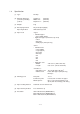
1.4 Specification (1) Type Desktop (2) External dimensions (excludes protruding portion) Height 6.3” Width 12.6” Depth 14.
(10) Power input 120 VAC +5.5%, –15% 230 VAC +15 %, –15% (11) Power consumption Peak: Typical operation: Idle: Power save mode: Approx. 420W Approx. 160W Approx. 55W Approx.
1.5 Safety Standards 1.5.1 Certification Label The safety certification label is affixed to the printer at the location described below.
1.5.2 Warning Label The warning labels are affixed to the sections which may cause bodily injury. Follow the instructions on warning labels during maintenance.
1.5.3 Warning/Caution Marking The following warning and caution markings are made on the power supply board. CAUTION ENGLISH Heatsink and transformer core present risk of electric shock. Test before touching. FRENCH Le dissipateur thermique et le noyau du transformateur présentent des risques de choc électrique. Testez avant de, manipuler. SPANISH Las disipadores de color el núcel del transformador pueden producir un choque eléctrico. Compruebe antes de tocar.
2.
2. OPERATION DESCRIPTION OKIPAGE 6e, OKIPAGE 6ex consists of a Main Control PCB, a power supply/sensor board, a PostScript board (OKIPAGE 6ex), an operator panel and an electrophotographic process mechanism. The soft operator panel is used for operation and status display of OKIPAGE 6e and OKIPAGE 6ex. The operator panel is used for operation and status display of OKIPAGE 6ex. The OKIPAGE 6e and OKIPAGE 6ex receive data via the host I/F, these then decode, edit and store the data in memory.
1MB Memory Board (Option) For optional L5D RAM board Resident RAM 1M x 16 DRAM(2M Bytes) L5C- or L5D Program & Font ROM 4MB Mask ROM L5C Resident RAM 256k x 16 DRAM x 2 (1M Bytes) 16 bits DATA BUS High Capacity Second Paper Feeder (Option) EEPROM Centronics parallel I/F Drum motor & Registration motor drive circuit M Drum Motor M Registration Motor 7407 1 Chip CPU FAN Driver FAN FAN ALM LED Head CH TR DB HEAT ON +8V -8V 0V +5V +30V Reset circuit Thermistor LSI Power Supply Board Inlet se
LocalTalk I/F (RS422 I/F) or PS Board with RAM 1MB Memory Board For optional RAM board L6A16 bit Program & Font ROM 4MB Mask ROM 32 bit DATA BUS 16 bit Resident RAM 1M x 16 DRAM (2MB) High Capacity Second Paper Feeder (Option) EEPROM Centronics parallel I/F Drum motor & Registration motor drive circuit M Drum Motor M Registration Motor 7407 1 Chip CPU FAN Driver FAN FAN ALM LED Head CH TR DB HEAT ON +8V -8V 0V +5V +30V Reset circuit Thermistor LSI Power Supply Board Inlet sensor 2 +5V
2.1 Control Board The control board consists of a single chip CPU, Program & Font ROM's, one or two DRAMs, an EEPROM, a host interface circuit, and a mechanism driving circuit. (1) Single chip CPU The single chip CPU is a custom CPU (32-bit internal bus, 16-bit or 32-bit external bus, 25.54 MHz clock with input frequency from a 12.
(3) DRAM OKIPAGE 6e/6ex The DRAM is a resident memory (OKIPAGE 6e: 1MB(L5C) or 2MB(L5D)/OKIPAGE 6ex: 2MB) used as a buffer, and it stores edited data, image data, DLL data and macro data. OKIPAGE 6ex with PS Board The DRAM is a resident memory (2MB on the OKIPAGE 6ex main board plus 0.5MB on the PS board) used as a buffer, and it stores edited data, image data, DLL data and macro data. In the Post Script emulation, it is used as VM and font cache also.
2.2 PS Board (OKIPAGE 6ex option) The PS board consists of two Program & Font ROM's, DRAM's, an EEPROM, and a host interface circuit. (1) Program & Font ROM's The Program & Font ROMs store the PostScript Level II program and its fonts. Mask ROM is used for the Program & Font ROMs. (2) DRAM 0.5MB of DRAM's reside on the PS board. (3) EEPROM 4.096 bit-Electrically Erasable PROM (EEPROM) is mounted on the PS board for storing the PostScript's menu settings.
2.3 RAM Board (OKIPAGE 6e/6ex option) The RAM board consists of DRAM's and a SIMM socket. (1) DRAM 1MB of DRAM's reside on the RAM board. (2) SIMM Socket One SIMM socket is mounted on the RAM board.
2.4 Power Supply Board The power supply board consists of an AC filter circuit, a low voltage power supply circuit, a high voltage power supply circuit, heater drive circuit, and photosensors. (1) Low Voltage Power Supply Circuit This circuit generates the following voltages.
The sensor layout diagram is shown in Figure 2-3. Exit roller Outlet sensor Heat roller Transfer roller Paper running direction Paper sensor Inlet sensor 1 Toner Inlet sensor sensor 2 Paper end sensor Registration roller Hopping roller Figure 2-5 Sensor Function Sensing state Inlet sensor 1 Detects the leading edge of the paper and gives the supervision timing for switching from hopping operation to feeding operation.
2.5 Electrophotographic Process 2.5.1 Electrophotographic Process Mechanism This mechanism actuates the printing of image data supplied by the control board on the paper by electrophotographic process. The layout of the electrophotographic process mechanism is shown in Figure 2-6.
Heat roller LED head Toner cartridge Developing roller Eject roller assy Charge roller Image drum unit Figure 2-6 2 - 11 Outlet sensor lever Paper cassette Back-up roller Cleaning roller Registration roller Inlet sensor lever Transfer roller Paper sensor lever Hopping roller
(1) Image Drum Unit The image drum unit consists of a sensitive drum, a charger, and a developer. The unit forms a toner image on the sensitive drum, using a electrostatic latent image formed by the LED head. (2) Registration Motor The registration motor is a pulse motor of 48 steps/rotation, that is two-phase excited by the signal from the Main Control PCB. It drives the hopping and registration rollers via two oneway clutches according to the direction of rotation.
2.5.2 Electrophotographic Process The electrophotographic processing is outlined below. The electrophotographic printing process is shown in Figure 2-7. 1 Charging The surface of the image drum is charged uniformly with a negative charge by applying the negative voltage to the charge roller. 2 Exposure Light emitted from the LED head irradiates the negatively charged surface of the image drum.
Paper eject roller Paper eject Image data (Face down) Power supply LED head Charger roller 2 - 14 Figure 2-7 Paper eject roller Power supply Power supply (Bias voltage) Doctor blade Exposure Toner cartridge Charging Paper path selector Paper eject Cleaning roller (Face up) Outlet sensor Inlet sensor Paper sensor Fusing Heater roller Paper eject Toner supply roller Developing roller Developing Cleaning Back-up roller Fusing Cleaning Power supply Transfer Paper registration Pap
PRINT-N PRDY-N DM-ON-N Figure 2-8 2 - 15 RM-ON INSNS OUTSNS-N Feed start Inlet Sensor OFF Outlet Sensor OFF Feed stop
2.5.3 Process Operation Descriptions (1) Hopping and Feeding Hopping and feeding motions are actuated by a single registration motor in the mechanism as shown below: Idle gear Registration motor Registration roller a Hopping roller b Registration gear Motor gear Hopping gear The registration motor turning in direction "a" drives the hopping roller. The registration motor turning in direction "b" drives the registration roller.
(a) Hopping 1 For hopping, the registration motor turns in direction "a" (CW direction) and drives the hopping roller to advance the paper until the inlet sensor turns on (in this case, the registration gear also turns, but the registration roller is prevented from turning by the one-way bearing). 2 After inlet sensor is turned on by the paper advance, the paper is further advanced to a predetermined distance until the paper hits the registration roller (the skew of the paper can thus be corrected).
(b) Feeding 1 When hopping is completed, the registration motor turning in direction "b" (CCW direction) drives the registration roller to advance the paper (in this case, the hopping gear also turns, but the hopping roller is prevented from turning by the one-way bearing). 2 The paper is further advanced, synchronization to the print data.
(2) Charging Charging is actuated by the application of the DC voltage to the charge roller that is in contact with the image drum surface. Power supply Charge roller Image drum The charge roller is composed of two layers, a conductive layer and a surface protective layer, both having elasticity to secure good contact with the image drum. When the DC voltage applied by the power supply exceeds the threshold value, charging begins.
(3) Exposure Light emitted by the LED head irradiates the image drum surface with a negative charge. The surface potential of the irradiated portion of the image drum drops, forming an electrostatic latent image associated with the image signal. Charge roller LED head LED head Power supply Image drum Paper Image drum The image drum is coated with an underlayer (UL), a carrier generation layer (CGL), and carrier transfer layer (CTL) on aluminum base.
The image roller surface is charged to about –750 V by the contact charge of the charge roller. When the light from the LED head irradiates the image drum surface, the light energy generates positive and negative carriers in the CGL. The positive carriers are moved to the CTL by an electrical field acting on the image drum. Likewise, the negative carriers flow into the aluminum layer (ground).
(4) Developing Toner is attracted to the electrostatic latent image on the image drum surface, converting it into a visible toner image. Developing takes place through the contact between the image drum and the developing roller.
Note: The bias voltage required during the developing process is supplied to the toner supply roller and the developing roller, as shown in the diagram below. –450 VDC is supplied to the toner supply roller, –300 VDC to the developing roller.
(5) Transfer The transfer roller is composed of conductive sponge material, and is designed to get the image drum surface and the paper in a close contact. Paper is placed over the image drum surface, and the positive charge, opposite in polarity to that of the toner, is applied to the paper from the reverse side.
(6) Fusing When the image transfer is completed, the toner image is fused to the paper by heat and pressure as the paper with unfused toner image passes between the heater roller and the back-up roller. The heater roller with Teflon coating incorporates a 400W heater (Halogen lamp), which heats the heat roller. A thermistor which is in contact with the heater roller regulates the temperature of the heater roller at a predetermined level (about 165°C).
(7) Cleaning When the transfer is completed, the residual toner left on the image drum is attracted to the cleaning roller temporarily by static electricity, and the image drum surface is cleaned. Image drum Cleaning roller Power supply Transfer roller (8) Cleaning of rollers The charge, transfer and cleaning rollers are cleaned for the following cases: • • • • Warming up when the power is turned on. Warming up after the opening and closing of the cover.
2.6 Paper Jam Detection The paper jam detection function monitors the paper condition when the power is turned on and during printing. When any of the following conditions arises, this function interrupts the printing process. If any of the following errors is encountered, printing can be recovered by removing the jammed paper (by opening the upper cover, removing the jammed paper and closing the upper cover).
Drum motor Registration motor Hopping Paper feed Paper feed Paper end sensor Inlet sensor Checking for paper form Paper size check (paper width) Paper sensor Outlet sensor Jam Monitor Top to top Top to bottom Monitoring paper input jam Monitoring paper feed jam Monitoring paper feed jam Paper size check (Paper length) Monitoring paper exit jam Top to bottom Monitoring Bottom to bottom paper feed jam Paper Feed Timing Chart 2 - 28
Paper Feed Check List Error Type of error Standard value Monitor Plus Minus Paper feed error Hopping start to Inlet sensor on 72.0 36.0 _ Paper feed jam Inlet sensor on to Write sensor on 20.0 20.0 _ Paper feed jam Write sensor on to Outlet sensor on 140.5 25.0 _ Paper size error Inlet sensor on to Inlet sensor off Depends on the paper length 45.0 45.0 Paper exit jam Outlet sensor on to Outlet sensor off Depends on the paper length 45.0 45.
2.7 Cover Open When the stacker cover is opened, the cover open microswitch on the power/sensor board is turned off to cut +5V supply to the high voltage power supply circuit. This results in the interruption of all high-voltage outputs. At the same time, the CVOPN signal is sent to the control board to notify that the microswitch is off, and the control board carries out the cover open process.
2.8 Toner Low Detection • Device The Toner Low Detection device consists of a stirring gear which rotates at a constant rate, a stirring bar and a magnet on the stirring bar. The stirring bar rotation is driven by the link to the protrusion in the stirring gear. Magnet Protrusion Stirring Bar • Stirring Gear Operation Toner Low is detected by monitoring the time interval of the encounter of the magnet set on the sensor lever and the magnet on the stirring bar.
TONER FULL state 240 ms < t1 < 1.5 sec TNRSNS-N t1 4.875 sec. TONER LOW state TNRSNS-N t1 t1 > 1.5 sec. or t1 < 240 ms 4.875 sec. • When the Toner Low state is detected 2 times consecutively, Toner Low is established. • When the Toner Full state is detected 2 times consecutively, Toner Low is cancelled. • When there is no change with the toner sensor for 2 cycles (4.875 sec. x 2) or more, then the Toner Sensor Alarm is activated.
3.
3. PARTS REPLACEMENT The section explains the procedures for replacement of parts, assemblies, and units in the field. Only the disassembly procedures are explained here. For reassembly, reverse the steps of disassembly procedure. 3.1 Precautions for Parts Replacement (1) Before starting the parts replacement, remove the AC power cord and interface cable. (a) Remove the AC power cord in the following sequence: i) ii) iii) (b) Turn off ("o") the power switch of the printer.
[Service Tools] The tools required for field replacement of printed circuit boards and units are listed in Table 3-1. Table 3-1 Service Tools No. Service Tools Q' ty 1 No. 1-100 Philips screwdriver 1 2 No. 2-100 Philips screwdriver 1 3 No. 3-100 screwdriver 4 No. 5-200 screwdriver 5 Digital multimeter 6 Pliers 7 Handy cleaner 8 LED Head cleaner 1 9 Maintenance Utility (Parts Number: 4YA4046-1722G1) 1 Place of use Remarks 2~2.
3.2 Parts Layout This section describes the layout of main parts of the equipment.
[Upper cover unit] Stacker Stacker clamp Upper cover Figure 3-2 3-4
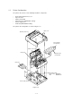
[Base unit] RAM board • LQME-PCB (OKIPAGE 6e/OKIPAGE6ex) Power supply DC fan assy Main Control PCB • L5C or L5D: OKIPAGE 6e • L6A : OKIPAGE 6ex Transformer Contact assy Paper cassette Figure 3-3 3-5
3.3 How to Change Parts This section explains how to change parts and assemblies listed in the disassembly diagram below. In the parts replacement procedure, those parts marked with the part number inside ● with white letters are RSPL parts. Printer unit Upper cover (3.3.1) Stacker (3.3.2) LED head (3.3.3) Eject roller assy (3.3.4) Pulse motor (Hopping) (3.3.5) Pulse motor (Resist) (3.3.6) Lower base unit (3.3.7) Motor assy (3.3.8) Hopping roller assy (3.3.9) Stacker cover assy (3.3.
3.3.1 Upper Cover (1) With the power switch turned off, unplug the AC power cord from the outlet. (2) Disconnect the interface cable 1. (3) Remove the option board D if it is mounted. (4) Lift the left side of the operator panel assy (or logo frame) 4 and remove it. (5) Disconnect the flexible cable 5 from the connector (CN1) 6 of the operator panel PCB 6, and put the cable inside the cover. (OKIPAGE 6ex only) (6) Open the stacker cover assy 9 by pressing the knobs 8 on the left and right sides.
3.3.2 Stacker (1) Remove the upper cover. (See 3.3.1) (2) Remove two stacker clamps 1 and the stacker 2 by bending the upper cover.
3.3.3 LED Head (1) Open the stacker cover. (2) Remove the flexible cable (LED) 1 from the PC connector 2 of the LED head 3. (3) Remove the LED head by prying the left side free from the retaining clip. Note: Be careful to not lose the contact (LED) 4. Note: • Be sure not to directly touch or push the SLA part of the LED head. • After mounting the new LED head, set drive time of the LED head according to the marking on the LED head (see 4.3.1 or 4.3.2).
3.3.4 Eject Roller Assy (1) Remove the upper cover (see 3.3.1). (2) Press the clamp on the left side of the eject roller assy 1 in the direction of the arrow. Detach the eject roller assy from the lower base unit 2, and remove it. Note: When installing the eject roller, verify the proper engagement with the main unit.
3.3.5 Pulse Motor (Main) (1) Remove the upper cover (see 3.3.1). (2) Remove the connector 3 from (CN2) 2 of the Main Control PCB 1. (3) Remove two screws 4 and remove the pulse motor (main) 6 from the motor bracket 5.
3.3.6 Pulse Motor (Registration) (1) Remove the upper cover (see 3.3.1). (2) Remove the connector 3 from (CN3) 2 of the Main Control PCB 1. (3) Remove two screws 4 and remove the pulse motor (registration) 6 from the motor bracket 5.
3.3.7 Lower Base Unit (1) Remove the upper cover (see 3.3.1). (2) Remove the connecting cables 4 and 5 of the pulse motor from the connectors 2 and 3 of the Main Control PCB 1. (3) Remove the connector 6 of the LED head from the Main Control PCB 1. (OKIPAGE 6e: 1 connector, OKIPAGE 6ex: 2 connectors) (4) Remove seven screws 7, then remove the lower base unit 8.
3.3.8 Motor Assy (1) Remove the upper cover (see 3.3.1). (2) Remove the lower base unit (see 3.3.7). (3) Stand the lower base unit on its side as shown, and unlock two clamp levers, then remove the motor assy 1.
3.3.9 Hopping Roller Assy (1) Remove the upper cover (see 3.3.1). (2) Remove the lower base unit (see 3.3.7). (3) Remove the motor assy (see 3.3.8). (4) With the lower base unit 1 standing on its side, remove the one-way clutch gear 2 and the bearing (A) 3, then remove the hopping roller assy 4 and the bearing (B) 5.
3.3.10 Stacker Cover Assy (1) Remove the upper cover (see 3.3.1). (2) Remove the motor assy (see 3.3.8). (3) Remove the reset lever R 1. (4) Detach the reset spring 2 from the lower base unit 3, turn the reset level L 4 in the direction of the arrow A until it stops, and remove it in the direction of the arrow B . (5) Release two pins of the lower base unit 3, then remove the stacker cover assy 5.
3.3.11 Registration Roller (1) Remove the upper cover (see 3.3.1). (2) Remove the lower base unit (see 3.3.7). (3) Remove the motor assy (see 3.3.8). (4) With the lower base unit standing on its side (view A), remove the one-way clutch gear 1. (5) Press the registration roller 2 to the right side (in the direction of the arrow as shown) and lift up the left side. Remove the registration roller 2 and the bearing (registration) 3.
3.3.12 Transfer Roller (1) With the power switch turned off, unplug the AC power cord from the outlet. (2) Open the stacker cover. (3) Release TR gear 1 by unlocking the latch 4 of the main unit (never apply an excessive force when unlocking the latch). (4) Lift the right side of the transfer roller 2, and shift it to the right side, then pull it out from the main unit (at this time, the bearings 3 of the left and right sides of the transfer roller 2 will release themselves).
3.3.13 Fusing Unit Assy (1) Remove the upper cover (see 3.3.1). (2) Remove the lower base unit (see 3.3.7). (3) Remove the stacker cover assy (see 3.3.10). (4) Remove four screws 1 and remove the fusing unit 2. Caution: Fusing unit assy may be hot. Use care when handling. Note: When installing or removing the fusing unit assy, tighten or loosen the screws while holding the fusing unit down with your hand.
3.3.14 Back-up Roller (1) Remove the fusing unit assy (see 3.3.13). (2) Lift the left side of the back-up roller 1, and pull it out to the left side (at this time, two bushings 2, the bias springs 3 and washers 4 and 5 will release themselves). Note: Do not bend or lose springs.
3.3.15 Sensor Plate (Inlet) (1) Remove the upper cover (see 3.3.1). (2) Remove the lower base unit (see 3.3.7). (3) Press the clamps of three sensor plates (inlet) 1, and remove the sensor plates by pressing them upward from the bottom side.
3.3.16 Toner Sensor (Adhesion) (1) Remove the upper cover (see 3.3.1). (2) Remove the lower base unit (see 3.3.7). (3) Press the clamp of the toner sensor 1, and remove the sensor by pushing it up from the bottom.
3.3.17 Sensor Plate (Outlet) (1) Remove the upper cover (see 3.3.1). (2) Remove the eject roller assy (see 3.3.4). (3) Remove the lower base unit (see 3.3.7). (4) Remove the fusing unit assy (see 3.3.13). (5) Press the clamp of the sensor plates (outlet) 1, and remove the sensor plate by pushing it up from the bottom.
3.3.18 Manual Feed Guide Assy (1) Remove the upper cover (see 3.3.1). (2) Open the manual feed guide assy 1, and release the engagement on both sides with the main unit by carefully bending the manual feed guide assy 1. Note: At the time of mounting, verify the proper the engagements as shown in the diagram. Put into the post. Put into the groove.
3.3.19 Sensor Plate (Paper Supply) (1) Remove the upper cover (see 3.3.1). (2) Remove the lower base unit (see 3.3.7). (3) Press the clamp of the sensor plate (paper supply) 1, and remove it from the base plate 2.
3.3.20 Main Control PCB Note: When replacing the Main Control PCB, the contents of the EEPROM shall be copied to the new PCB. This process requires a maintenance utility. (See 4.3.1 4 and 4.3.2 4 for details.) • The Main Control PCB is different for each model. OKIPAGE 6e : L5C or L5D OKIPAGE 6ex : L6A (1) Remove the upper cover (see 3.3.1). (2) Remove the lower base unit (see 3.3.8). (3) Remove two screws 1. (4) Move the Main Control PCB 2 in the direction of arrow supply board 3.
3.3.21 Power Supply Board and Contact Assy (1) Remove the upper cover (see 3.3.1). (2) Remove the lower base unit (see 3.3.7). (3) Remove the Main Control PCB (see 3.3.20). (4) Remove the AC inlet 1 from the inlet holder 2, and remove the connector 3 of the transformer. (5) Remove the screws 4, and remove the ground cable 5. (6) Remove three screws 6, and remove the power supply board 7 and contact assy 8 at the same time. (7) Unlock two claws 9, and remove the contact assy 8 from the power supply board 7.
3.3.22 Transformer (1) Remove the upper cover (see 3.3.1). (2) Remove the lower base unit (see 3.3.7). (3) Remove the connectors (CN1 and CN2). (4) Remove the inlet 3 from the inlet holder 2. (5) Remove two screws 1, and remove the inlet holder 2 and the transformer 4.
3.3.23 Cassette Guide L (1) Remove the paper cassette. (2) Remove the upper cover (see 3.3.1). (3) Remove the lower base unit (see 3.3.7). (4) Remove the Main Control PCB (see 3.3.20). (5) Remove the power supply board (see 3.3.21). (6) Remove the screw 1, and remove the cassette guide L 2 by shifting it in the direction of the arrow. (7) Detach the eject spring 3, and remove the support spring 4 from the cassette guide L 2.
3.3.24 Cassette Guide R (1) Remove the paper cassette. (2) Remove the upper cover (see 3.3.1). (3) Remove the lower base unit (see 3.3.7). (4) Remove the Main Control PCB (see 3.3.20). (5) Remove the screw 1, and remove the cassette guide R 2 by shifting it in the direction of the arrow. (6) Pull the eject spring 3 out of the cassette guide R 2, then remove the support spring 4.
4.
4. ADJUSTMENT 4.1 Adjustment (OKIPAGE 6e) This chapter describes the adjustment necessary when replacing a part. The adjustment is made by changing the parameter value set in EEPROM on the Main Control PCB by means of a printer driver or by a maintenance utility program. The maintenance utility is designed to be used only by field engineer and it should not be released to the end-users. 4.1.
2 Maintenance utility Maintenance utility has following functions. (1) Engine Menu For setting the engine menu. (2) Engine Counter Reset For resetting the engine counter. (3) Status Monitor For real time display of the printer status. (4) Test print For local print or test print. (5) Reload For reading out the printer setting information. (6) Option Other functions. Fig. 4-2 shows the Main Menu Dialog.
2-1 Engine Menu The following functions can be set in the Engine Menu. (1) Print Position For adjusting print start position. (2) LED Head Marking No. For adjusting LED Head marking duration. (3) LED Head Width For stipulating number of LED dots. (4) Optical head The mounting head type is set. (5) Head type The adjustment method for the adjustment head for 600 DPI is set. (6) Page PRT Valid or invalid of page count print of menu print is set. (7) Wait table The standby temperature 150°C or 135°C is set.
2-2 Engine Counter The following functions can be set in the Engine Counter. Each item is reset by clicking of the "Reset" button. (1) Drum Count The number of drum revolution of the EP drum unit, counted at the engine block. (2) Total Drum Count The total number of drum revolution of the printer, counted at the engine block. (3) Page Count The total number of printed pages counted at the engine block. (4) Reset All Resetting all counters by clicking of the button.
(5) Print File It performs a test file print. Printer emulation is stipulated by a file suffix. xxx.HBP (Hiper-W emulation) xxx.BIN (PCL emulation) xxx.PRN (Ditto) xxx.aaa (Ditto: aaa may be any strings other than the above.) Figure 4-3 2-5 Option Menu Button It performs operation selected in the Option Button Menu. Available operations are as follows. (1) Reset Engine It resets all the Engine Menu contents to the factory default setting.
(4) Product set Product (ID) of the printer is set. Product which is available at present is only MDL (Model). Up to 32 alphanumeric characters can be inputted. The corresponding type is the type supporting the ID down- load command. For an unsupported type, no character can be inputted as light color display. (5) Printer name set The corresponding type is changed.
2-6 Correspondence to non-corresponding product ID printer When the ID of the printer is not corresponding, a dialog for selecting the corresponding printer name is displayed. When the printer name is set, it is registered in the initialization file and processed as a corresponding printer also for the next and subsequent startup. The following is a display example of a printer set dialog. Figure 4-5 The following five types of printer names can be set.
2-7 Reload Button The same setting as in the starting up of an application software can be made. It reads out the settings of the printer being connected. It is used to change the printer while running the same application program on the PC. 2-8 About Button It displays information on the Maintenance Utility and the printer firmware. Figure 4-6 2-9 Exit Button It ends the Maintenance Utility.
2-10 Setup Dialog The Setup Dialog is displayed when "Setup" is selected from the system menu items on the Main Menu Dialog. In the Setup Dialog, selection of printer languages and printer port is available. Figure 4-7 (1) Printer Port For selecting a printer port. (2) Cancel For canceling the setting and returning to the Main Menu Dialog. (3) OK For initializing the settings to reflect all the settings in the menu.
4.2 Adjustment (OKIPAGE 6ex) This chapter describes the adjustment necessary when replacing a part. The adjustment is made by changing the parameter value set in EEPROM on the Main Control PCB. The parameter can be set by the key operation from the operator panel. This printer has three kinds of maintenance modes, and it is necessary to select one of the modes when replacing a part. 4.2.
3 Engine Maintenance Mode Note: This mode is used only by service persons, and it should not be released to the end users. To enter into the engine maintenance mode, turn the POWER switch on while holding the FORM FEED and ENTER keys down.
4.3 Adjustment When Replacing a Part 4.3.1 Adjustment at the Time of Part Replacement (OKIPAGE6e: 300dpi LED head) The following table lists parts that require adjustment after replacement. Parts 1 Required Adjustment LED head LED head drive time Image drum unit Drum counter reset (Refer to the user's manual for details.) Control P.C.B.
OKIPAGE6e • Setting of LED Head Drive Time Drive time of the LED head is set by setting the parameter of drive time of EEPROM according to the luminous intensity marking on the LED head. a.
4.3.2 Adjustment When Replacing a Part (OKIPAGE6ex: 600dpi LED head) Adjustment is necessary when replacing any one of the following parts. Parts 1 Required Adjustment LED head LED head drive time Head Type Image drum unit Drum counter reset (Refer to the User's Manual.) Main Control Board EEPROM data Upload/Download (See 4.3.1 4.
OKIPAGE6ex • Setting of LED Head Drive Time Drive time of the LED head is set by setting the parameter of drive time of EEPROM according to the luminous intensity marking on the LED head. a.
Setting Example: Method for setting the parameter to 19 (for case where the previous parameter setting was 8). Operation Turn the POWER switch on while holding the FORM FEED and ENTER keys down. Press the MENU key. Press + or - key, until "19" is displayed. Press the ENTER key. LCD display after operation ENG MNT OPT HEAD 600-4W LED HEAD No. 8 * The item of “OPT HEAD” is always 600-4W when the 600dpi head is used. Displays previous parameter No. LED HEAD No. 19 LED HEAD No.
4.3.3 Uploading/Downloading EEPROM data When the controller printed circuit board is replaced, the contents of the old EEPROM shall be copied to the new EEPROM on the new board to preserve customer settings. For the purpose, use the EEPROM operation on the Option of the Maintenance Utility. (See Fig. 4-4.) To copy follow the steps below. (1) Be sure to confirm that the printer and the PC are connected with a centronics I/F cable. Then execute the Maintenance Utility.
5.
5. PERIODICAL MAINTENANCE 5.1 Periodical Replacement Parts The parts are to be replaced periodically as specified below: Part name 5.2 Condition for replacement • Toner cartridge About 2,000 sheets of paper have been printed. • Image drum cartridge About 20,000 sheets of paper have been printed. Cleaning Remarks • LED head. Consumables Consumables Cleaning Remove any toner or dust accumulated inside the printer. Clean in and around the printer with a piece of cloth when necessary.
(1) Set the LED head cleaner to the LED lens array as shown in the figure, then slide the cleaner back and forth horizontally several times to clean the head. Note: Gently press the LED head cleaner onto the LED lens array. LED head cleaner LED lens array (2) Throw the cleaner away.
6.
6. TROUBLESHOOTING PROCEDURES 6.1 Troubleshooting Tips (1) Check the basic check points covered in the user’s manual. (2) Gather as much information about the problem from the customer as possible. (3) Inspect the equipment under the conditions close to those in which the problem had occurred. 6.
6.4 Preparation for Troubleshooting (1) PC display (OKIPAGE 6e) The failure status of the printer is displayed by the display of the PC. Take proper corrective action as directed by messages which are being displayed on the display of the PC. There are 4 types of LED display status: On, Normal blinking, Fast blinking and Off. Type Function Remarks On On-line (Ready), Warming up Normal blinking Data receiving ~ Printing 0.5 sec. interval Fast blinking Recoverable alarm (paper end, cover open, etc.
6.5 Troubleshooting Flow Should there be a problem with the printer, troubleshoot according to the following procedure flow: Problems Problems indicated by error message Troubleshoot from the status message list. See 6.5.1. Image troubles (and troubles which are not indicated by message) 6.5.1 Carry out a detailed troubleshooting with the troubleshooting chart. See 6.5.2. Carry out a troubleshooting with the troubleshooting chart. See 6.5.3.
Table 6-1 Category PC display status message Trouble or status Controller errors Controller Error An error occured in the controller. Program ROM Check Error Remedy – Normal operation cannot be ensured. Turn the power off, then back on to restart. – If normal operation is not recovered by this restart procedure, replace the Main Control PCB. An error was detected by program – Replace the Main Control PCB. ROM check. – When replacing the Main Control PCB, upload/download the EEPROM data. (Refer to 4.3.
Table 6-1 (Cont'd) Category PC display status message Trouble or status Remedy Controller errors Optional Software ROM An error was detected by optional Check the optional software ROM Check Error software ROM check. board for proper connection or replace it. An error was detected by optional – Check the optional RAM board Optional RAM Check RAM check. for proper connection. Error – Check the mounting position of short plugs and additional RAM chips. (See 7.4.) – Replace the optional RAM board.
Table 6-1 (Cont'd) Category PC display status message Trouble or status Controller errors Second Tray Timeout I/F timeout occured between the Error Main Control Board and the 2nd Tray. I/F timeout occured between the Multipurpose Feeder Main Control Board and the multi Timeout Error feeder. Watch Dog Timeout Error A watch dog timeout occured. Cover Open Cover Open Jam errors Paper Input Jam The upper cover was opened. Remedy Check the 2nd tray for proper connection.
Table 6-1 (Cont'd) Category Jam errors PC display status message Paper Feed Jam Paper Exit Jam Paper size error Paper Size Error Trouble or status Remedy A jam occured during paper feeding – Check the paper in the cassette. after completion of paper hopping Open and then close the cover. from the tray being displayed. When the cover is closed, recovery printing is carried out and the error display is released. – If this error occurs frequently, see 6.5.2 2-2. Jam occured during paper ejecting.
Table 6-1 (Cont'd) Category Tray paper out Tray# Paper Out Size errors Tray# #Paper Request Buffer overflow PC display status message Trouble or status Remedy The tray being displayed has run Load paper in the tray. out of paper. Tray# : Standard Tray, Second Tray, Multipurpose Feeder # : Executive, Letter, Legal14, Legal13, A4, A5, A6, B5, Monarch, COM-10, COM-9, DL, C5 Loading of paper indicated by the Load the requested paper in the tray. second line message to the first line's tray is requested.
Table 6-1 (Cont'd) Category Buffer overflow Daily status PC display status message Send Buffer Overflow Print Overrun Error Ready Warming Up Initializing Ready Ready Power Saving Printing Demo Printing Menu Printing Fonts Printing Ejecting Trouble or status Remedy The send buffer is overflowing. Normal operation The printer overrun because the print data is too complicated to be printed. The printer is warming up.
Table 6-1 (Cont'd) Category Daily status PC display status message Manual Paper In Reset Ready Toner Low Ready Toner Sensor Problem Toner Sense Ready Change Drum Unit Trouble or status Remedy There is a paper on the manual tray. The data which remained unprinted in the buffer is deleted and the printer is initialized to user default settings. The temporary DLLs and macro are deleted. Toner is running out. – Replace the toner cartridge. Normal operation can be continued.
Table 6-2 Category Controller errors LCD status message ERROR 0n aaaaaaaa Trouble or status An error occurred in the controller. n = Exception Code aaaaaaa = Error Address Remedy – Normal operation cannot be ensured. Turn the power off, then back on to restart. – If normal operation is not recovered by this restart procedure, replace the Main Control PCB. An error occurred in the controller. – Turn the power off, then back on to recover from the error.
Table 6-2 (Cont'd) Category Controller errors LCD status message ERROR nn Trouble or status Code Error (nn) 0n A fault occurred in the controller. n = Exception Code 10 An error was detected by program ROM check. 20 An error was detected by font ROM check. 30 An error was detected by resident RAM check. 40 An error was detected by EEPROM check. 50 An error was detected by optional software ROM check. 6 - 12 Remedy Remedy Replace the Main Control PCB. Replace the Main Control PCB.
Table 6-2 (Cont'd) Category Controller errors LCD status message ERROR nn Trouble or status Code Error (nn) 60 An error was detected by optional RAM check. 70 71 72 73 74 80 Remedy Remedy – Check the optional RAM board for proper connection. – Check the mounting position of short plugs and additional RAM chips (see 7.4). – Replace the option RAM board. A fault occurred in the Fan – Check the fan motor for proper motor. connection and for any presence of foreign matter in the fan (see 6.5.2-5).
Table 6-2 (Cont'd) Category Controller errors LCD status message ERROR nn Cover open COVER OPEN Jam errors tray INPUTJAM Trouble or status Remedy Code Error Remedy (nn) 81 I/F timeout occurred between Check the optional tray for proper the Main Control PCB and connection. the optional tray (2nd tray, envelope feeder, etc.). 90 A watchdog timer timeout – Turn the power off, then back occurred. on to recover from the error. – Replace the Main Control PCB. 91 Invalid CPU was used. – Check valid CPU list.
Table 6-2 (Cont'd) Category Jam errors LCD status message tray FEED JAM PAPER EXIT JAM Paper size error tray SIZE ERR Tray paper out tray PAPEROUT Trouble or status Remedy A jam occurred during paper feeding – Open the cover, remove the after completion of paper hopping paper, then close the cover. from the tray being displayed. When the cover is closed, recovery printing is carried out tray: TRAY 1, TRAY 2, FEEDER and the error display is released. – If this error occurs frequently, see 6.5.2 2-2.
Table 6-2 (Cont'd) Category Size error LCD status message tray #REQUEST MANUAL #REQUEST Trouble or status Loading of paper indicated by the second line message to the first line's tray is requested. tray: TRAY 1, TRAY 2, FEEDER #: LETTER, EXECUTIV, LEGAL 14, LEGAL 13, A4 SIZE, A5 SIZE, A6 SIZE, B5 SIZE, FREE SIZE Manual loading of paper indicated by the second line message is requested.
Table 6-2 (Cont'd) Category Buffer overflow LCD status message REC BUFF OVERFLOW Trouble or status The receive buffer is overflowing. – – (for OKIPAGE 6ex, in HP 4 mode) – PAGE BUF OVERFLOW The page buffer is overflowing because it received too much data for printing on the page. (for OKIPAGE 6ex, in HP 4 mode) DLL BUFF OVERFLOW – The DLL buffer is overflowing. – Press the operator panel RECOVER key to release the error display. – Install additional optional RAM board or reduce the DLL data.
Table 6-2 (Cont'd) Category Daily status LCD status message OFF-LINE emulate PROCS'NG Trouble or status The printer is in the off-line mode. The second line indicates the emulation. emulate: HP4, AdobePS Post Script mode only. The printer is processing data (OKIPAGE6ex in PS mode) WAITING Post Script mode only. The printer is in the middle of a job and waiting for data to be processed. (OKIPAGE6ex in PS mode) PRINTING The printer is printing a page. 6 - 18 Remedy Normal operation.
Table 6-2 (Cont'd) Category Daily status LCD status message DATA HP4 (for OKIPAGE6ex, in HP 4 mode) Trouble or status The printer is processing data in on-line mode. Ready ON: The data that is not printed remains in the buffer. PRINT FONTS Ready flashing: The printer is receiving data. All fonts of the printer are being printed during self-test. PRINT MENU The current menu setting is being printed. Ready ON: Executed by command entry. Ready flashing: Executed by key operation.
Table 6-2 (Cont'd) Category Daily status LCD status message PRINT DEMO nnn/mmm CPYnn/mm (for OKIPAGE6ex, in HP 4 mode) PR BUSY (OKIPAGE6ex in PS mode) Trouble or status The demo page is being printed. When the number of copies being printed is two or more, the number of copies being printed is displayed. This message is displayed together with another message on the first line.
Table 6-2 (Cont'd) Category Daily status LCD status message RESET TO FLUSH (OKIPAGE6ex in PS mode) FLUSHING Trouble or status Post Script mode only This message is displayed when ON-LINE key is pressed while the printer is processing the job, if the JOB RESET menu is ON. (for OKIPAGE6ex, in HP 4 mode) - Press RESET key. The job is cancelled. Even while this message is being displayed, the printer continues to process processing the job normally. Normal operation.
Table 6-2 (Cont'd) Category Daily status LCD status message RESET TO SAVE (for OKIPAGE6ex, in HP 4 mode) TONERLOW Trouble or status Remedy This message is displayed when the Normal operation. printer cannot reset automatically to exit from the menu because there are data and DLL's and macros having temporary attributes when the printer is changed from set mode to other mode. Toner is running out. – Replace the toner cartridge. This message is displayed together with other message on the first line.
Table 6-2 (Cont'd) Category Daily status LCD status message PWR SAVE Trouble or status The printer is in the power-saving mode. Remedy Normal operation. This message is displayed together with other message on the first line. – Check the printer setting of the PostScript mode only host. This message will appear when the interpreter detects an error during a – Check the printer job data to see (OKIPAGE6ex in PS mode) job processing.
6.5.2 Status Message Troubleshooting If the problems are not correctable by using the status message trouble list, follow the troubleshooting flowcharts given here to deal with them. No. Trouble Flowchart number 1. The printer does not work normally after the power is turned on. 1-1 (OKIPAGE 6e) 1-2 (OKIPAGE 6ex) 2. Jam alarm Paper input jam 2-1 Paper feed jam 2-2 Paper exit jam 2-3 3. Paper size error 3 4. Fusing unit error 4 5.
The printer does not work normally after the power is turned on. (OKIPAGE 6e and OKIPAGE 6ex) • Turn the power off, then back on. • Is LED turned on? • No Is the AC cable being connected properly? • No Connect the connection properly. ▼ • Yes Is +5 V being applied between pins 2 and 5 of CN5 on the Main Control PCB? Pin 2 : 0 V Pin 5 : +5 V B ▼ 1-1 • No Is the connection between connector CN7 on the control board and connector CN3 on the power supply board made properly? No Correct the connection.
▼ A ▼ • Take the measurement of the following voltages at connector CN2 on the power supply board: Voltage between pins 1 and 3: ... about 28 V AC Voltage between pins 5 and 6: ... about 10 V AC Are the voltages normal? • Yes Is fuse F3 on the power supply board open? • No Replace the power supply board. ▼ • Yes Replace fuse F3 (if it blows again, check the resistance of the registration and drum motors (see 7.3).
The printer does not work normally after the power is turned on. (OKIPAGE 6ex PS mode) • Turn the power off, then back on. • Is all ■'s message being displayed by the LCD display? ■■■■■■■■ ■■■■■■■■ • No Is the AC cable being connected properly? • No Connect the cable properly.
• Yes Replace the Main Control PCB. ▼ • Remedy? • Yes End ▼ • No ▼ A ▼ • Take the measurement of the following voltages at connector CN2 on the power supply board: Voltage between pins 1 and 3: ... about 28 V AC Voltage between pins 5 and 6: ... about 10 V AC Are the voltages normal? • Yes Is fuse F3 on the power supply board open? • No Replace the power supply board. ▼ • Yes Replace fuse F3 (if it blows again, check the resistance of the registration and drum motors (see 7.3).
[JAM error] Paper input jam • Does the JAM error occur when the power is turned on? • Yes Is the paper at the inlet sensor? • Yes Remove the paper. ▼ • No Is the operation of the inlet sensor lever normal (moves freely when touched)? • No Replace the inlet sensor lever. ▼ • Yes ▼ • No Clean the inlet sensor on the power supply board, or replace the power supply board.
[JAM error] 2-2 Paper feed jam • Does the paper feed jam occur when the power is turned on? • Yes Is the paper on the paper sensor lever? • Yes Remove the paper. ▼ • No Is the operation of the paper sensor lever normal (moves freely when touched)? • No Replace the paper sensor lever. ▼ • Yes ▼ • No Replace the power supply board. Has the paper reached the paper sensor lever? • No Is the registration roller rotating? • No Replace the one-way clutch gear.
2-2-a 2-2-b ▼ • Yes ▼ • Yes • No ▼ • Yes • No ▼ •Yes Is the transfer roller rotating? Check the gears (TR gear, idle gear and reduction gear). Is the fuser unit being installed properly? Install the fuser unit properly. Is the image drum unit being set properly? • No ▼ Replace the Main Control PCB. • Yes Set the image drum unit properly. Clean the write sensor on the power supply board or replace the power supply board.
[JAM error] 2-3 Paper exit jam • Does the paper exit jam error occur when the power is turned on? • Yes Is the paper on the outlet sensor lever? • Yes Remove the paper. ▼ • No In the operation of the outlet sensor lever normal (moves freely when touched)? • No Replace the outlet sensor lever.
Paper size error • Is paper of the specified size being used? • No ▼ • Yes Use paper of the specified size. Are inlet sensor levers 1 and 2 operating properly (moves freely when touched)? • No ▼ • Yes Replace the inlet sensor lever or clean the inlet sensor on the power supply board. Does the outlet sensor lever operate properly (moves freely when touched)? • No ▼ • Yes Replace the outlet sensor lever or clean the outlet sensor on the power supply board. Replace the power supply board.
4 Fusing unit error (ERROR 71) (ERROR 72) (ERROR 73) • Turn the power off, then back on. • Does the fusing unit error occur immediately? • Yes Is the thermistor open or shorted? Measure the resistance between thermistor contacts (about 220kΩ at room temperature) (see Fig. 6-2 or see 7.3). • Yes Replace the fusing unit. Heater contacts Themistor contacts Figure 6-2 ▼ • No Do the thermistor contacts touch the contact assembly properly when the fusing unit is mounted in the printer (see Fig.
5 Fan error (ERROR 70) • Is the fan rotating? • Yes ▼ • No Is connector CN1 on the Main Control PCB being connected? • No ▼ Replace the Main Control PCB. • Yes Connect connector CN1. Replace the fan or Main Control PCB (check coil resistance of the fan, See 7.3).
6.5.3 Image Troubleshooting Procedures for troubleshooting for the cases of abnormal image printouts are explained below. Figure 6-3 below shows typical abnormal images.
1 Images are light or blurred entirely. • Is toner low (is the TONER LOW message displayed)? • Yes ▼ • No Supply toner. Is paper of the specified grade being used? • No ▼ • Yes Use paper of the specified grade. Is the lens surface of the LED head dirty? • Yes ▼ • No Clean the lens.
2 Dark background density • Has the image drum been exposed to external light? • Yes ▼ • No Mount the image drum in the printer and wait about 30 minutes. Is the heat roller of the fusing unit dirty? • Yes ▼ • No Clean the heat roller. Is the contact of the cleaning roller of the image drum unit in contact with the contact assembly properly (see Fig. 6-4 C )? • No ▼ • Yes Adjust the contact of the cleaning roller to make a proper contact with the contact assembly. Replace the image drum unit.
4 Black vertical belts or stripes • Replace the image drum unit. • Has the problem been removed? • Yes End Note: ▼ • No After replacing the image drum unit, set the printer in the user maintenance mode by turning the power on while pressing the MENU key, and reset the drum counter (see User’s Manual). Replace the LED head. • Has the problem been removed.
5 Cyclic error Frequency Remedy Image drum 3.71” (94.2 mm) Replace or clean the image drum unit. Developing roller 1.66” (44.4 mm) Replace the image drum unit. Toner supply roller 2.27” (57.8 mm) Replace the image drum unit. Charging roller 1.56” (39.6 mm) Replace the image drum unit. Cleaning roller 1.24” (31.4 mm) Replace the image drum unit. Transfer roller 2.01” (51.0 mm) Replace the transfer roller. Heat roller 2.47” (62.8 mm) Replace the fusing unit assy. Back-up roller 2.
6 Print voids • Is the contact plate of the transfer roller in proper contact with the power supply board (see Fig. 6-5)? • No ▼ • Yes Adjust the contact plate so that it touches the power supply board and the shaft of the transfer roller properly. Replace the transfer roller. • Has the problem been removed. • Yes ▼ • No End Are the contacts of the toner supply roller, developing roller, image drum and charging roller in proper contact with the contact assy (see Fig.
7 Poor fusing • Is paper of the specified grade being used? • No ▼ • Yes Use paper of the specified grade. Is the spring of the back-up roller normal? • No ▼ • Yes Replace the spring. Is the contact of the fusing unit assy in proper contact with the contact assy (see Fig. 6-4 G )? • No ▼ • Yes Adjust the contact of the fusing unit assy to make a proper contact with the contact assembly. Replace the fusing unit assy.
8 White vertical belts or streaks • Are the LED lens dirty? • Yes ▼ • No Clean the LED lens. Is the contact plate of the transfer roller in proper contact with the power supply board (see Fig. 6-5)? • No ▼ • Yes Adjust the contact plate to make a proper contact with the power supply board. Replace the transfer roller.
Figure 6-4 6 - 44 A B C D E G F F G C r sto rmi The istor rm The r AC te a e H ler Rol rge a h C rum) nd (D r Grou olle ing R r Clean ing Rolle lop ller o R Deve pply r Su Tone He ate rA cts nta Co
Contact plate for transfer roller Contact Power supply board Figure 6-5 6 - 45
7.
7-1 Fuse F1 F2 F3 AC Main Voltage Fuse Rating L FG N To Heater F1 CN3 125V 6.3A 250V 5A 125V 1.6A Non 125V 3.15A 250V 2.
7-2 Fuse F1 F2 F3 AC Main Voltage Fuse Rating L FG N 1 2 3 4 1 2 3 4 230V ACSW CN1 CN2 CN3 To Heater F1 CN3 125V 6.3A 250V 5A 125V 1.6A Non 125V 3.15A 250V 2.
7.
(2) Power Supply Board 26 25 1 2 (3) PS Board (LQ8A-2) (OKIPAGE 6ex) 7-4
• CN1 Pin Assignment To Fan motor Opening • PIN NO. I/O Signal Description 1 1 O FANPOW Power supply for fan driving 2 2 C OV Ground 3 3 I FANALM-N Fan alarm PIN NO. I/O Signal 1 1 O DMPH1-N Coil 1-N 2 2 O DMPH1-P Coil 1-P 3 3 O DMPH2-N Coil 2-N 4 4 O DMPH2-P Coil 2-P CN2 Pin Assignment To Drum motor Description Excitation sequence Step No. PIN NO.
• CN3 Pin Assignment To Regist motor PIN NO. I/O Signal Description 1 1 O RMPH1-N Coil 1-N 2 2 O RMPH1-P Coil 1-P 3 3 O RMPH2-N Coil 2-N 4 4 O RMPH2-P Coil 2-P Excitation sequence Step No. PIN NO. Line Color 1 2 3 4 2 Yellow + - - + 4 Black + + - - 1 Orange - + + - 3 Brown - - + + Turning direction Clockwise as viewed from the output axis.
• CN4 Pin Assignment To LED head 1 2 3 4 5 6 7 8 9 10 11 12 13 14 OKIPAGE 6e Signal Description PIN NO.
• HEAD1 & HEAD2 Pin Assignment To LED head OKIPAGE 6ex HEAD1 1 2 3 4 5 6 7 8 9 10 11 12 13 14 HEAD2 1 2 3 4 5 6 7 8 9 10 11 12 PIN NO.
• CN6 Pin Assignment To Option feeder PIN NO.
• POWER Pin Assignment (To power supply/sensor board) Pin No. Signal I/O Description Pin No.
• CN8 Pin Assignment Centro Parallel Pin No. I/O* Signal Description Pin No.
• CN11 Pin Assignment To Option board and PS board 41 01 42 02 43 03 44 04 45 05 46 06 47 07 48 08 49 09 50 10 51 11 52 12 53 13 54 14 55 15 56 16 57 17 58 18 59 19 60 20 61 21 62 22 63 23 64 24 65 25 66 26 67 27 68 28 69 29 70 30 71 31 72 32 73 33 74 34 75 35 76 36 77 37 78 38 79 39 40 80 Pin No.
PS Board (OKIPAGE6ex) • CN1 Pin Assignment To LocalTalk (RS422) PIN NO.
PS Board (OKIPAGE6ex) • CN2 Pin Assignment To Main Control PCB 01 41 02 42 03 43 04 44 05 45 06 46 07 47 08 48 09 49 10 50 11 51 12 52 13 53 14 54 15 55 16 56 17 57 18 58 19 59 20 60 21 61 22 62 23 63 24 64 25 65 26 66 27 67 28 68 29 69 30 70 31 71 32 72 33 73 34 74 35 75 36 76 37 77 38 78 39 79 80 40 Pin No.
7.3 Resistance Check Circuit Diagram Unit 1 Illustration Resistance Orange M 2 Registration motor 3 4 1 Yellow Between pins 1 and 2: 18.6Ω Between pins 3 and 4: 18.6Ω Brown Black Orange M 2 Main (drum) motor 3 4 1 Fusing Unit Yellow Between pins 1 and 2: 12.6Ω Between pins 3 and 4: 12.
Unit Circuit Diagram 1 Illustration Red White White Yellow Transformer 1 Resistance Primary side Between pins 1 and 2: 56.8Ω (OEL) 14.8Ω (ODA) 3 5 Secondary side 2 Fan Black Primary side Red 1 +30 V White 3 FANALM-N Black Secondary side 6 Between pins 1 and 3: 1.3Ω Between pins 5 and 6: 1.
7.4 Short Plug Setting (1) Main Control Board • OKIPAGE 6e • OKIPAGE 6ex : L5C-PCB : L6A-PCB L5C- • L6A- Short plug settings Short plug Plug setting Description SP2 3 +5 V is supplied to pin 18 of Centronics parallel I/F connector. 1 High level is supplied to pin 18 Centronics parallel I/F connector.
(2) Option RAM Board (LQME-PCB) 7 - 18
• SIMM specification Usable RAM capacity: 1/2/4/8/16/32 Mbytes (Access time 60 ~ 100 ns) • Short Plug Setting Printer SP1 SP2 Remarks OKIPAGE 6e Side B Side B See remark for SIMM capacity limitation. OKIPAGE 6ex Side A Side A • Relation between the capacity of added SIMM and total effective RAM capacity is shown in table below. OKIPAGE 6e OKIPAGE 6ex SIMM Capacity Total Capacity SIMM Capacity Total Capacity Nil. 2 Mbytes Nil. 3 Mbytes 1 Mbyte 3 Mbytes 1 Mbyte 4 Mbytes 2 Mbytes 3.
8.
8.
Table 8-1 Lower Base Unit No.
1 OKIPAGE 6ex 8-3 8-4 1-2 1 1-5 OKIPAGE 6e 1-3 1-7 8-1 8-2 1-1 1-4 1-8 1-4 1-6 Figure 8-2 Upper cover unit 8-3
Table 8-2 Upper cover unit No. Name/Rating Part No.
I L J 8 0 6 7 H F 9 C 3 5 A 4 E 4 E K 1 M 2 D Figure 8-3 Base unit 8-5
Table 8-3 Base unit No. Name/Rating Part No.
Appendix A CENTRONICS PARALLEL INTERFACE 1) Connector • Printer side : • Cable side : 36-pin receptacle (single port) Type 57-40360-12-D56 (made by Daiichi Denshi) or equivalent 36-pin plug Type 57-30360 (made by Daiichi Denshi) or equivalent Plug-552274-1 (AMP), 552073-1 (AMP) or equivalent 2) Cable • IEEE std 1284-1994 compliant cable is recommended for noise prevention. • Cable length : 6 ft (1.8 m) max. Note: Cable is not supplied.
3) Table of parallel I/F signals Signal Direction Logic Compatible Nibble ECP Functions Data Strobe → Printer Negative nStrobe Host Clk HostClk Data strobe 2-9 Data Bit n ↔ Printer Positive 10 Acknowledge Printer → Negative PeriphClk Completion of reception or function 11 Busy Printer → Positive Busy PtrBusy PeriphAck Data reception not possible 12 Paper End Printer → Positive PError AckDataReq nAckReverse No paper 13 Select Printer → Positive Select Xllag Xfla
• 4) Connector pin arrangement Signal level • • Low High : 0 V to +0.8 V : +2.4 V to 5.0 V 5) Modes IEEE 1284 • Compatible mode • Nibble mode • ECP mode 6) Data bit length 8 bits 7) Receiving buffer Varies depending on option RAM size. 8) Control Data is received from the host, and stored in the reception buffer. Block busy control is carried out. Signal line is also carried out. 9) Interface circuit a) Receiving circuit +5V R R = 3.3KΩ (1.0-KΩ Strobe) b) Sending circuit +5V 3.
&'./$%,-"#*+674523 10) Timing charts a) Data receiving timing • Compatible mode PARALLEL DATA (DATA BITs 1 to 8) 0.5 µs min. 0.5 µs min. 0.5 µs min. DATA STROBE 0.5 µs min. 0 min. 0.5 µs max. BUSY 0 min. 0 min. ACKNOWLEDGE 0.5 µs to 10 µs 0 min. b) Data Receiving Timing (Burst Mode) PARALLEL DATA DATA STROBE 1 µs min. 1 µs min.
d) On-line -> off-line switching timing by ON-LINE SW (HP4 emulation) ON-LINE SW BUSY SELECT 50 ms max. e) Off-line -> on-line switching timing by ON-LINE SW (HP4 emulation) ON-LINE SW BUSY SELECT ACKNOWLEDGE 0 min. 100 ms max. 0.5 µs to 10 µs f) INPUT PRIME timing (when set to the effective INPUT PRIME signal.) 50 µs min. INPUT. PRIME BUSY SELECT 5 µs max. 0 min. ACKNOWLEDGE 5 µs max. 0.
11) Interface Parameter Setting (OKIPAGE 6ex) The following settings are possible by pressing ENTER Copies contents of the LCD of the operator panel by using NEXT Demo key, after selecting the display + and LAST Paper Size keys. Settings are retained even when the printer power is turned off. By pressing ON-LINE key, menu setting mode is completed and the printer returns to ON- LINE state.
Press ON-LINE key. Setting completed.
Appendix B LOCALTALK (RS422) SERIAL INTERFACE 1) Connector • Printer side • Cable side : 8-pin mini DIN receptacle Type TCS7187-01-201 (made by HOSHIDEN) or equivalent : 8-pin mini DIN plug Type TCP7180-01-110 (made by HOSHIDEN) or equivalent 2) Cable • • To be shielded cable Cable length LocalTalk Defined max. length : 1,000 ft. (305 m) (It is the maximum length for a LocalTalk network.) Recommended max. length : 10 ft. (3 m) (For noise prevention) RS422 : 6 ft. (1.8 m) max.
• Connector Pin Arrangement 8 7 5 6 4 2 3 1 (As viewed from the cable side) 4) Signal level Differential output : ±5V Differential input : ±7V 5) Interface circuit a) Receiving circuit 26LS30 or equivalent + DIFFERENTIAL OUTPUT - INPUT ENABLE b) Transmitting circuit 26LS32 or equivalent DIFFERENTIAL INPUT + - 6) Receive margin 7) Communication protocol • LocalTalk I/F LocalTalk protocol • RS422 I/F X-ON/X-OFF protocol B-2 OUTPUT
8) Interfacing parameter setting The following settings are possible by pressing ENTER PowerSave contents of the LCD of the operator panel by using key after selecting the display Reset and Recover keys. Settings are retained even when the printer power is turned off. By pressing ON-LINE key, menu setting mode is completed and the printer returns to ON-LINE state.
a) LocalTalk ↔ RS422 switching Ready Press OFF-LINE Adobe PS MENU 1 Menu 2 key for 2 seconds to enter the menu mode (level 2), then press key, 7 times. Ready Press ENTER PowerSave Ready Press ADOBE PS SETUP MENU 1 Menu 2 key. JAM RECV key, 6 times.
Item ACTIV 422 Selection Function LOCALTK LocalTalk I/F RS422 RS422 I/F Factory Setting: LOCALTK Ready Press ON-LINE Ready key. ON-LINE Adobe PS Setting completed.
b) RS422 I/F parameter setting Ready OFF-LINE Adobe PS MENU 1 Menu 2 Keep key down for more than 2 seconds and bring the printer into menu setting mode (level 2). Next, press Ready Press MENU 1 Menu 2 RS422 SERIAL ENTER PowerSave Ready key, 8 times. key.
MENU 1 Menu 2 Press key. Item Selection 8 BITS 7 BITS Factory Setting: 8 bit Ready Press MENU 1 Menu 2 key. Item PARITY Selection Function NONE No parity EVEN Even parity ODD Odd parity Factory Setting: No parity Ready Press ON-LINE Ready DATABITS Function 8 bit length 7 bit length key. ON-LINE Adobe PS Setting completed.
Appendix C 1. 1.1 DIAGNOSTICS TEST Maintenance Modes • The maintenance modes consist of the user maintenance mode opened to the user, and the system and engine maintenance modes for service personnel level. • Press the Menu key to update each category. The operation returns to the first category after updating the last category. • Press the Enter key to select and/or execute the function being displayed.
(4) X-Adjust / Y-Adjust • This function sets the first character printing position on the first line. • The operation mode starts automatically upon completion of resetting. (5) Operator Panel Menu Disable • This function is for enabling and disabling of the operation panel menu functions (Menu 1, Menu 2, Tray Select, Copies and Paper Size). LCD display USER MNT MENU RESET Press the Menu key. Press the Enter key. Press the Menu key. Press the Enter key.
1.2 System Maintenance Mode (1) The system maintenance mode is set when the power is turned ON while keeping the Recover key pressed down. (2) This mode adopts the menu for function selection. (3) The method for exit from this mode depends on the setting. (4) The system maintenance mode provides the following functions: (a) Page count display • The total number of pages counted at the engine block is displayed on the LCD.
• The following items are excluded: Head drive time setting Fine adjustment of printing start position Standard tray paper feed amount setting • Transition to the operation mode occurs upon completion of resetting. • Press the Menu key to update each category. The operation returns to the first category after updating the last category. (1) System Maintenance Mode Menu System LCD display SYS MNT Press the Menu key. PAGE CNT nnnnnn Press the Menu key. Press the PAGE PRT DISABLE * + or - key.
1.3 Engine Maintenance Mode (1) The engine maintenance mode is activated when the power is turned ON while keeping the Form Feed key and Enter key pressed down. (2) This mode adopts the menu for function selection. (3) The method for exit from this mode depends on the setting. (4) The engine maintenance mode provides the following functions: (a) Head type setting • Set the type of the LED head. (300-1W or 300-2W or 600-4W) (b) Head drive time setting • Sets the drive time of the LED head.
(j) Standard tray paper feed setting • Do no change its default setting since this is a factory setting and were set at the factory. (k) Second tray paper feed setting • (l) Do no change its default setting since this is a factory setting and were set at the factory. Second tray download table selection • Do not change its default setting since this is a factory setting and were set at the factory.
• Engine maintenance mode menu system LCD display ENG MNT OPT HEAD 300-1W * Press the + or - key. 600-4W Press the Menu key. LED HEAD No. 25 * Press the + or - key. Press the Menu key. HEAD WID NARROW * Press the Menu key. HEAD TYPE TYPE 2D4* 300-1W * 300-2W Press the + or - key. Press the + or - key. No. 9 No. 10 . No. 25 . No. 40 * Writing into the EEPROM is carried out after pressing the Enter key. (Note: Be sure to select "300-1W" for OKIPAGE 6e and to select "600-4W" for OKIPAGE 6ex.
Press the + or - key. T2 POS 0 mm * Press the Menu key. Press the + or - key. T2 TBL No. 3 * Press the Menu key. EF POS 0 mm * Press the + or - key. Press the Menu key. EF TBL 1 No. 3 * Press the + or - key. Press the Menu key Be sure to check that it is set to 0 mm. No. 1 No. 2 No. 3 Be sure to check that it is set to No. 3. * 0 mm * + 1 mm . + 7 mm - 8 mm . - 1 mm Be sure to check that it is set to 0 mm. No. 1 No. 2 No. 3 Be sure to check that it is set to No. 3.
1.4 Factory User Setting Operation • Switching of ODA, OEL, and OKI-INT users settings is possible with the factory user setting operation. • The user factory user setting operation is carried out by turning the power ON while keeping both the Menu key and the NEXT+ or LAST- key pressed down. (1) Factory ODA Setting Operation: Turn the power ON while keeping the Menu key and NEXT+ key press down. (2) Factory OEL Setting Operation: Turn the power ON while keeping the Menu key and LAST- key pressed down.
Appendix D 1. MAINTENANCE UTILITY OVERVIEW OVERVIEW A Maintenance Utility for the OKI LED printers (hereinafter referred to as the Maintenance Utility) is an application program that runs on the Microsoft Windows 3.1 and Windows 95. It is a software designed to set various settings such as printer engine menu, counter initialization, etc. by sending environment setting command selected by the operator. Environment setting languages transmitted is OPEL (Oki Print Environment Language) and PJL.
1.3 Software Configuration The Maintenance Utility consists of the following files. (1) Maintenance Utility ("MNTDRV.EXE") The Maintenance Utility executable file. It handles user interface (display control) and handling of messages transmitted from the Windows. (2) Initialization File ("MNTDRV.INI") Data such as menu setting of the Maintenance Utility and the command analysis library, etc. The file is used for initialization of the program. (3) Command analysis library ("OPEL.DLL", "PJL.
2. MAIN MENU DIALOG When the Maintenance Utility is triggered, it reads out menu setting, counter data and version data to display on the Main Dialog Box to prompt operator input. Maintenance items are grouped for display in the following manner.
2.1 Engine Menu Group In the Engine Menu Group, following items may be set. (1) Print Position Display Print Position Setting item Correct print start position. Setting range –4.00 mm ~ +3.5 mm F/W default 0.00 mm (2) LED Head Drive Time Display LED Head Marking No. Setting item Adjust LED head marking time. Setting range –37 ~ 505 – 545 F/W default 155 – 167 (3) LED Head Width (OKIPAGE 6e) Display LED Head Width Setting item Select number of LED Head dot numbers.
(5) Optical head Display Optical Head Setting item Setting of mounting head type Setting range D-300-1W(300DPI) / D300-2W(300DPI adjustment) / D D-600-4W(600DPI) F/W default D300-1W(OKIPAGE 6e) / D600-4W(OKIPAGE 6ex) (6) Head type (OKIPAGE 6ex) Display HEAD TYPE Setting item The adjustment method for the adjustment head for 600DPI is set.
(9) Enter The values set at the time of the clicking of the "Enter" button is entered as a new setting value. (10) Cancel The value set at the time of the clicking of the "Cancel" menu is cleared. 2.2 Engine Counter Group In the Engine Counter Group, following items may be set. (1) Drum Count It displays the number of drum revolution of the EP drum unit, counted at the engine block. (2) Total Drum Count It displays the total number of drum revolution of the printer, counted at the engine block.
2.3 Status Monitor It monitors the printer status and displays the status in real time. For display messages, refer to the table below.
Paper Request Status Message Tray1 paper request Standard Tray Paper# Request Tray2 paper request Second Tray Paper# Request Manual paper request Manual Paper# Request Feeder paper request Multipurpose Feeder Paper# Request Paper#: Exective Letter Legal 14 Legal 13 Ledger A6 A5 A4 A3 B5 B4 Monarch COM-10 DL C5 JIS B5 C4 COM-9 Message: Executive Paper Letter Paper Legal14" Paper Legal13" Paper Ledger Paper A6 Paper A5 Paper A4 Paper A3 Paper B5 Paper B4 Paper Monarch Envelope Com-10 Envelope DL En
Jam & Size Error Status Message Paper Size Error Paper Size Error Input Jam Paper Input Jam Feed Jam Paper Feed Jam Exit Jam Paper Exit Jam Recoverable Alarm Status Message Page Buffer Overflow Page Buffer Overflow Macro Buffer Overflow Macro Buffer Overflow DLL Buffer Overflow DLL Buffer Overflow Receive Buffer Overflow Receive Buffer Overflow Send Buffer Overflow Send Buffer Overflow Print Overrun Print Overrun D-9
Unrecoverable Error Status Message Controller Error Controller Error Program ROM Check Error Program ROM Check Error Font ROM Check Error Font ROM Check Error Resident RAM Check Error Resident RAM Check Error EEPROM Check Error EEPROM Check Error Option ROM Check Error Option Software ROM Check Error Option RAM Check Error Option RAM Check Error Fan Motor Error Fan Motor Error Fuser Error Fuser Error Thermister Error Thermister Error Thermister Open Thermistor Open Check Error Thermi
2.4 Test Print Button It diaplys the Test Print Dialog and performs local print or test file print. 2.4.1 Local Print Upon selection of button, it transmits local print command to the printer. No. 2.4.2 Item Print Test Item 1 Menu Status Print Menu Print 2 Demonstration Demo Print 3 Printer Available Font Print Font Print 4 Change Roller Cleaning Print Charge Roller Cleaning Test File Print It opens the File selection Dialog box (Windows API) to wait for print file input by an operator.
2.5 Option Button It displays the Option Menu Dialog. For details, refer to 3. Option Menu Dialog. 2.6 About Button It opens the About Dialog box to display information on the Maintenance Utility and the printer firmware. 2.7 Reload Button It performs the same operation as that of the program start up. It reads out printer menu settings and counter values. This function is mainly used to copy the settings of previous printer into newly replaced printer or newly replaced main control board.
2.8 Exit Button It ends the Maintenance Utility. Before it closes, it shows a dialog box to confirm whether to renew the setting when the menu settings displayed on the Engine Menu and the User Default Environment do not match. When "Yes" is selected: It writes the setting of the Menu in the EEPROM of the printer and terminates the program. When "No" is selected: It terminates the program without writing the setting of the Engine Menu in the EEPROM of the printer.
3. OPTION MENU DIALOG It displays the Option Menu Dialog and performs functions listed on the menu. Option Menu items are grouped into three categories. (1) EEPROM Operation It displays and sets the Engine menu settings. (2) H/W Check It checks the printer hardware. (3) Product set Product (ID) of the printer is set. (4) Printer name set The corresponding type is changed. 3.
3.2 EEPROM Upload Button It reads out the Engine Menu setting and the Counter data of the printer being connected and store the data in RAM of the PC. When the data is stored in RAM of the PC, "EEPROM Download" button becomes effective. 3.3 EEPROM Download Button It sends the Engine Menu setting and the Counter setting data to the printer to set EEPROM when the "Upload button" has been clicked. 3.4 RAM Check Button (Not supported) 3.
4. SETUP DIALOG The Setup Dialog is displayed upon selection of "Setup" in the Main Menu Dialog. Environment setting language selection and printer port selection are made on the menu. The figure below shows a typical Setup Dialog. (1) Printer Language It designates printer environment setting language. (2) Add (Not supported) It adds new printer environment setting language. (3) Printer Port It designates printer port. (4) Cancel The value set at the time of the clicking of the "Cancel" menu is cleared.
Appendix E Multi-Purpose Feeder Maintenance E-1
PREFACE This Maintenance Manual is intended for the service person and describes the field maintenance methods for Multi-Purpose Feeder option of OKIPAGE 6e Series LED Page Printer. Refer to the Printer Handbook for equipment handling and operation methods.
CONTENTS 1. OUTLINE ................................................................................................ E - 4 1.1 1.2 2. MECHANISM DESCRIPTION ................................................................ E - 5 2.1 2.2 3. Functions ...................................................................................... E - 4 External View and Component Names......................................... E - 4 General Mechanism ..................................................................
1. OUTLINE 1.1 Functions This optional Multi-Purpose Feeder is installed on the front section of the printer, and it supplies paper automatically through the operation of pulse motor, which is driven by signals sent from the printer. The main functions are: • Paper that can be used: [Paper Types] • Standard Paper: • Special Paper: • Cut Sheet Size: Xerox 4200 (20-lb) OHP sheets (for PPC), label sheets (PPC sheets) * Not guaranteed for OHP sheets with attachments on the edge or reverse side.
2. MECHANISM DESCRIPTION 2.1 General Mechanism The Multi-Purpose Feeder feeds the paper into the printer by receiving the signal from the printer, which drives the pulse motor inside the Multi-Purpose Feeder, and this motion is conveyed to rotate roller-A and B. The paper is delivered from the separator into the printer. Once delivered into the printer, the paper is then controlled and fed through by pulse motor (Registration) of the printer. 2.
3. PARTS REPLACEMENT This section covers the procedures for the disassembly, reassembly and installations in the field. This section describes the disassembly procedures, and for reassembly procedures, basically proceed with the disassembly procedures in the reverse order. 3.1 Precautions Concerning Parts Replacement (1) Parts replacements must be carried out, by first turning the printer power switch off “O” and removing the Multi-Purpose Feeder from the printer.
[Service Tools] Table 3-1 shows the tools required for the replacement of printed circuit boards and units in the field. Table 3-1 Service Tools No. Q'ty Service tools 1 No. 1-100 Philips screwdriver 1 2 No. 2-100 Philips screwdriver 1 3 N0. 3-100 screwdriver 1 4 N0. 5-200 screwdriver 1 5 Digital multimeter 1 6 Pliers 1 7 Handy cleaner 1 E-7 Place of use 2 ~ 2.
3.2 Parts Layout This section describes the layout of the main components.
3.3 Parts Replacement Methods This section describes the parts replacement methods for the components listed in the disassembly order diagram below. Multi-Purpose Feeder Link (3.3.1) Separator (3.3.2) OLEV-11 PCB (3.3.3) Stepping motor (3.3.4) Planet gear (3.3.5) Roller-A (3.3.
3.3.1 Link (1) Open paper feed cover 1, and disengage the paper feed cover 1 and Link 3, while lifting the paper hold 2. (2) Remove the paper hold 2 off the arm 4. (3) Disengage the link 3 from the arm 4, and remove it. * Be careful not to damage the link and arm.
3.3.2 Separator (1) Turn the power switch off “O” and remove the connector cord. (2) Disengage the link and paper feeder cover (see 3.3.1). (3) Remove the 2 screws 1, disengage the locks at 2 locations on the upper frame 2 with a screwdriver, and remove the upper frame 2. (4) Remove the 2 screws 3, and take out the separator assembly 4.
3.3.3 OLEV-11 PCB (1) Remove the upper frame (see 3.3.2 steps (1) through (3)). (2) Remove the connector 1. (3) Remove the 2 screws 2, and remove the OLEV-11 PCB 3. When mounting the printed circuit board, be careful to make sure that the sensor plate is being set correctly.
3.3.4 Pulse Motor (1) Remove the upper frame (see 3.3.2 steps (1) through (3)). (2) Remove the OLEV-11 PCB (see 3.3.3). (3) Remove the 2 screws 1, and remove the stepping motor 2.
3.3.5 Planet Gear (1) Remove the upper frame (see 3.3.2 steps (1) through (3)). (2) Remove the OLEV-11 PCB (see 3.3.3). (3) Remove the 2 screws 1, and remove the motor bracket assembly 2 and planet gear 3.
3.3.6 Roller-A and B While only the removal procedure for roller-A is described here, the removal procedure for rollerB is basically same. When removing roller-B, however, be careful not to deform the sensor lever. (1) (2) (3) (4) (5) (6) Remove the upper frame (see 3.3.2 steps (1) through (3)). Remove the separator assembly (see 3.3.2). Remove the OLEV-11 PCB (see 3.3.3). Remove the motor bracket (see 3.3.5). Remove the gear 1.
4. TROUBLESHOOTING 4.1 Precautions Prior to the Troubleshooting (1) Go through the basic checking items provided in the Operator Guide. (2) Obtain detailed information concerning the problem from the user. (3) Go through the checking in the conditions similar to that in which the problem occurred. 4.2 Preparations for the Troubleshooting (1) Display on the operator panel The status of the problem is displayed on the LCD (Liquid Crystal Display) on the operator panel.
[ OEL/INT ] 1.
Status message display Ready LED display : OFF : ON : BLINKING : Undefined E - 18
4.3 Troubleshooting Method When a problem occurs, go through the troubleshooting according to the following procedure. Problem occurs Problem displayed by the message 4.3.1 Troubleshooting according to the Status Message List (see 4.3.1) Carry out detailed troubleshooting according to the Troubleshooting Flow (see 4.3.1) LCD Status Message List The listing of the statuses and problems displayed in the form of messages on the LCD or PC display is provided in Table 4-1.
• ( JAM error ) Paper Inlet Jam • Does paper jam at the inlet when the power is turned on? • YES Is the paper located above the sensor plate (Inlet)? • YES ▼ • NO Is the sensor plate (Inlet) operating normally? • NO ▼ • YES ▼ • NO Remove the paper. Replace the sensor plate (Inlet). Replace the power supply board or inlet sensor.
5. CONNECTION DIAGRAM 5.
5.
6.
Table 6-1 Multi-Purpose Feeder No. Description Oki-J Part No. ODA Part No.
Appendix F High Capacity Second Paper Feeder Maintenance F-1
PREFACE This Maintenance Manual is intended for the service person and describes the field maintenance methods for High Capacity Second Paper Feeder option of OKIPAGE 6e Series LED Page Printer. Refer to the Printer Handbook for the equipment handling and operation methods.
CONTENTS 1. OUTLINE ................................................................................................ F - 4 1.1 1.2 2. MECHANISM DESCRIPTION ................................................................ F - 5 2.1 2.2 3. Functions ...................................................................................... F - 4 External View and Component Names......................................... F - 4 General Mechanicsm..................................................................
1. OUTLINE 1.1 Functions The printer is mounted on top of this High Capacity Second Paper Feeder, and it supplies paper automatically through the operation of pulse motor (Hopping), which is driven by signals sent from the printer. The main functions are: • Paper that can be used: [Paper Type] • Standard Paper: • Cut Sheet Size: • Special Size: Xerox 4200 (20-lb) Use of envelopes, OHP sheets, label sheets and thick paper is not possible.
2. MECHANISM DESCRIPTION 2.1 General Mechanicsm The High Capacity Second Paper Feeder feeds the paper into the printer by receiving the signal from the printer, which drives the pulse motor inside the High Capacity Second Paper Feeder. This motion is converyed to rotate the One-way clutch of the hopping shaft assembly. The paper is delivered from the hopper into the printer through the turning of the hopping shaft assembly.
3. PARTS REPLACEMENT This section covers the procedures for the assembly, disassembly and installations in the field. This section describes the disassembly procedures, and for assembly procedures, basically proceed with the disassembly procedures in the reverse order. 3.1 Precautions Concerning Parts Replacement (1) Parts replacements must be carried out, by first turning the printer power switch off “O” and removing the High Capacity Second Paper Feeder from the printer.
[Service Tools] Table 3-1 shows the tools required for the replacement of printed circuit boards and units in the field. Table 3-1 Service Tools No. Q'ty Place of use Service tools 1 No. 1-100 Philips screwdriver 1 2 No. 2-100 Philips screwdriver 1 3 N0. 3-100 screwdriver 1 4 N0. 5-200 screwdriver 1 5 Digital multimeter 1 6 Pliers 1 7 Handy cleaner 1 F-7 2 ~ 2.
3.2 Parts Layout This section describes the layout of the main components.
3.3 Parts Replacement Methods This section describes the parts replacement methods for the components listed in the disassembly order diagram below. High Capacity Second Paper Feeder Pulse motor (hopping) (3.3.1) OLEV-12 PCB (3.3.2) Hopping roller shaft assembly and One-way clutch gear (3.3.
3.3.1 Pulse Motor (Hopping) (1) Turn the printer power switch off “O” and remove the interface cable. (2) Remove the paper casette 1. (3) Open the Front cover 2, stand the High Capacity Second Paper Feeder vertically and remove the 2 E-clamps 3. (4) Remove the 2 levers 4, and remove the tension springs 5. (5) Pull out the sheet guide 6 to the front. (6) Remove the 6 screws 7, and remove the front support plate 8. (7) Remove the connector 9 and the 2 screws 0, and remove the pulse motor A.
3.3.2 OLEV-12 PCB (1) Remove the front support plate (see 3.3.1 steps (1) through (6)). (2) Remove the connector 1, and the 2 screws 2, then remove the OLEV-12 PCB 3.
3.3.3 Hopping Roller Shaft Assembly and One-way Clutch Gear (1) Open the front cover 1. (2) Remove the 2 screws 2, and remove the hopping roller frame 3 (be careful not to lose the Springs 4 when you do this, since it comes off). (3) Remove the One-way clutch gear 5. (4) Remove the bush-A 6, and remove the hopping roller shaft assembly 7 (be careful not to lose the bush-B 8 when you do this, since it comes off).
4. TROUBLESHOOTING 4.1 Precautions Prior to the Troubleshooting (1) Go through the basic checking items provided in the Operator Guide. (2) Obtain detailed information concerning the problem from the user. (3) Go through the checking in the conditions similar to that in which the problem occurred. 4.2 Preparations for the Troubleshooting (1) Display on the Operator panel The status of the problem is displayed on the LCD (Liquid Crystal Display) on the Operator panel.
[ OEL/INT ] F - 14
Logo print Status message display Ready LED display : OFF : ON : BLINKING : Undefined F - 15
4.3 Troubleshooting Method When a problem occurs, go through the troubleshooting according to the following procedure. Problem occurs Problem displayed by the message 4.3.1 Troubleshooting according to the Status Message List (see 4.3.1) Carry out detailed troubleshooting according to the Troubleshooting Flow (see 4.3.1) LCD Status Message List The listing of the statuses and problems displayed in the form of messages on the LCD or PC display is provided in Table 4-1.
• ( JAM error ) Paper Inlet Jam • Does paper jam at the inlet when the power is turned on? • YES Is the paper located above the sensor plate (Inlet)? • YES ▼ • NO Is the sensor plate (Inlet) operating normally? • NO ▼ • YES ▼ • NO Remove the paper. Replace the sensor plate (Inlet). Replace the power supply board or inlet sensor.
5. CONNECTION DIAGRAM 5.
5.
6.
Table 6-1 High Capacity Paper Feeder No. Description Oki-J Part No. 1 Hopping roller shaft 3PP4083-6020P1 2 One-way clutch gear 4PB4083-6024P1 3 Pulse motor 4 ODA Part No. Q’ty Remark 1 Same as the printer unit. 51228901 1 Same as the printer unit.
OKI Data Corporation 11-22, Shibaura 4-chome, Minato-ku, Tokyo 108, Japan Tel: +81 (Japan)-3 (Tokyo)-5445-6159 Fax: +81-3-5445-6188 Printed in Japan