59389401_cvr.
Copyright Information Copyright © 2007 by Oki Data. All Rights Reserved Document Information ___________________ Microline 1120 User’s Guide P/N 59389401, Revision 1.1 April, 2007 Disclaimer_____________________________ Every effort has been made to ensure that the information in this document is complete, accurate, and up-to-date. The manufacturer assumes no responsibility for the results of errors beyond its control.
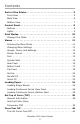
Contents Parts of the Printer . . . . . . . . . . . . . . . . . . . . . . . . . . . . . . . . 5 Front View . . . . . . . . . . . . . . . . . . . . . . . . . . . . . . . . . . . . . . 5 Back View . . . . . . . . . . . . . . . . . . . . . . . . . . . . . . . . . . . . . . 6 Bottom View. . . . . . . . . . . . . . . . . . . . . . . . . . . . . . . . . . . . . 7 Control Panel . . . . . . . . . . . . . . . . . . . . . . . . . . . . . . . . . . . . 8 Buttons . . . . . . . . . . . . . . . . . . . . . . . . . .
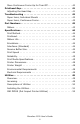
Move Continuous Forms Up for Tear Off. . . . . . . . . . . . . . . . . 40 Printhead Gap . . . . . . . . . . . . . . . . . . . . . . . . . . . . . . . . . . . 41 Adjusting the Head Gap . . . . . . . . . . . . . . . . . . . . . . . . . . . . 41 Troubleshooting . . . . . . . . . . . . . . . . . . . . . . . . . . . . . . . . . 42 Paper Jams, Individual Sheets . . . . . . . . . . . . . . . . . . . . . . . 42 Paper Jams, Continuous Forms . . . . . . . . . . . . . . . . . . . . . . . 42 Part Numbers . . . . . . .
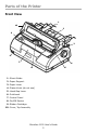
Parts of the Printer Front View F1_24_front.jpg 1 10 2 9 3 8 7 4 6 1. Sheet Guide 2. Paper Support 3. Paper Lever 4. Platen Knob (do not use) 5. Head Gap Lever 6. Printhead 7. Control Panel 8. On/Off Switch 9. Ribbon Cartridge 10.
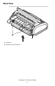
Back View F1_24_back.jpg 1 2 1. Tractors 2.
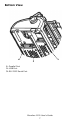
Bottom View F1_24_bottom.jpg 1 2 1. Parallel Port 2. USB Port 3.
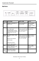
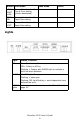
Control Panel Buttons panel.jpg Button Print mode Menu mode Other SEL Toggles the printer on and off line Scrolls through the menu groups Held at power up, places printer in Menu mode LF/FF Advances the paper one line. Held down, advances paper to the next top of form or ejects single sheet from the printer When entering Menu SEL + LF/FF mode, prints the first selects font line. Scrolls through the menu items. LOAD/ No paper loaded: feeds paper.
Button Print mode LOAD/ EJECT +SEL Menu mode Other Forward fine line feed for Top of Form setting (printer deselected) TEAR + Reverse fine line feed for SEL Paper Tear setting TEAR + Forward fine line feed for LF/FF Paper Tear setting Lights panel.
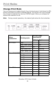
Print Modes Change Print Mode You can change print modes directly from the front panel. Hold down the SEL button and press the button indicated below. The printer will cycle through the choices as indicated by the two STATUS lights. When you release the buttons the selection is set. Nota During normal operation, the status lights show the font selection. panel.
Menus The printer has an internal menu containing a number of default parameters which can be set to enable your printer to match the parameters required by your computer. Entering the Menu Mode To enter the Menu Mode, press SEL while turning on the printer. Changing Menu Settings 1. Press SEL while turning on the printer. 2. Change settings: a. Press SEL to select the relevant group that needs to be changed (the group is the left-hand column on the Menu printout). b.
Groups, Items, and Settings Each Group includes multiple Items, each of which has selectable Settings.
Font Nota The default setting is in bold blue italic type. Item Settings Print Mode Utility NLQ Courier NLQ Gothic DRAFT DRAFT Mode HSD SSD Pitch 10 CPI 12 CPI 15 CPI 17.1 CPI 20 CPI Proportional Spacing No Yes Style Normal Italics Size Single Double * * Selects double width and double height characters.
Symbol Sets Nota The default setting is in bold blue italic type.
Rear Feed Nota The default setting is in bold blue italic type. Item Line Spacing Settings 6 LPI 8 LPI Form Tear-off Manual 0.5 sec 1.0 sec 2.0 sec Note: The Form Tear Off feature allows you to advance continuous forms to the stacker for tear off. When Form Tear-off is activated (on), the paper will advance to the tear bar position AFTER the printer has been idle for the selected interval (0.5, 1, or 2 seconds).
Item Settings TOF adjust (continuous) 0 - 20 ~ - 1 + 1 ~ +20 Continuous paper top of 2.12 mm (1/12”) form 4.23 mm (2/12”) 6.35 mm (3/12”) 8.47 mm (4/12”) 10.58 mm (5/12”) 12.70 mm (6/12”) 14.82 mm (7/12”) 16.93 mm (8/12”) 19.05 mm (9/12”) 21.17 mm (10/12”) 23.28 mm (11/12”) 25.40 mm (12/12”) 27.
Bottom Feed Nota The default setting is in bold blue italic type. Item Line Spacing Settings 6 LPI 8 LPI Skip Over Perf. No 25.4 mm (1”) Page Length 279.4 mm (11") 296.3 mm (11.67") 304.8 mm (12") 355.6 mm (14") 431.8 mm (17") 127.0 mm (5”) 76.2 mm (3") 82.6 mm (3.25") 84.7 mm (3.33”) 88.9 mm (3.5") 93.1 mm (3.67”) 101.6 mm (4”) 139.7 mm (5.5") 152.4 mm (6") 177.8 mm (7") 203.2 mm (8") 215.9 mm (8.
Top Feed Nota The default setting is in bold blue italic type. Item Line Spacing Settings 6 LPI 8 LPI Page Length 279.4 mm (11") 296.3 mm (11.67") 304.8 mm (12") 355.6 mm (14") 431.8 mm (17") 127.0 mm (5”) 76.2 mm (3") 82.6 mm (3.25") 84.7 mm (3.33”) 88.9 mm (3.5") 93.1 mm (3.67”) 101.6 mm (4”) 139.7 mm (5.5") 152.4 mm (6") 177.8 mm (7") 203.2 mm (8") 215.9 mm (8.5") Top Feed Wait Time Invalid 0.5 sec 1.0 sec 2.
Item Cut Sheet top of form Settings 2.12 mm (1/12”) 4.23 mm (2/12”) 6.35 mm (3/12”) 8.47 mm (4/12”) 10.58 mm (5/12”) 12.70 mm (6/12”) 14.82 mm (7/12”) 16.93 mm (8/12”) 19.05 mm (9/12”) 21.17 mm (10/12”) 23.28 mm (11/12”) 25.40 mm (12/12”) 27.
Set-Up Nota The default setting is in bold blue italic type.
Item Settings SI Select Pitch (10 CPI) 15 CPI 17.1 CPI SI Select Pitch (12 CPI) 12 CPI 20 CPI Valid Time Out Print Invalid Yes Auto Select No Auto Interface Host Interface Parallel USB Serial 15 sec I/F Time Out 30 sec 45 sec 1 min. 2 min. 3 min. 4 min. 5 min. ESC SI Pitch 17.
Item Settings Power Saving Enable Disable Power Save Time 5 min 10 min 15 min 30 min 60 min Paper End On-line Off-line Parallel I/F Nota The default setting is in bold blue italic type.
Serial I/F Nota The default setting is in bold blue italic type. Item Settings Parity None Odd Even Ignore Serial Data 7/8 Bits 8 Bits 7 Bits Protocol DTR X-ON/X-OFF DTR & X-ON/X-OFF Diagnostic Test No Yes Baud Rate 9600 BPS 4800 BPS 2400 BPS 1200 BPS 600 BPS 300 BPS 19200 BPS DTR Signal Ready on Power Up Ready on Select Busy Time 0.2 sec 1.
Loading Paper Loading Single Sheets 1. If continuous form paper is in the printer, press the LOAD/EJECT button to move it out of the paper path.If not, make sure the printer is on and on line (SEL light lit). 2. Move the paper lever—on the right side of the printer—toward the front of the printer to the single sheet symbol. F4_13.jpg 3. Raise the paper separator. F2_39.
4. Adjust the left sheet guide on the paper separator so that it touches the triangle mark on the paper separator. F4_01.jpg 5. Adjust the right sheet guide for the width of the paper. 6. Place a piece of paper on the paper separator. The printer will automatically feed it to the top of form position.
Loading Continuous Forms, Rear Feed 1. Make sure the printer is turned off. 2. Move the paper lever—on the right side of the printer—toward the front of the printer to the continuous forms symbol. icon_forms.jpg 3. Place the stack of continuous forms paper behind the printer. 4. Push down and out to remove the paper separator along with the piece on the back of the printer that holds it in place. F4_65.
5. Pull the lock levers on the sprocket wheels forward and open the sprocket covers. F4-35.jpg 6. Adjust the wheels so the sprockets align with the holes in the continuous forms you are using. F4-36.jpg 7. Close the sprocket covers and push the levers back to lock the sprocket wheels in position. 8. Replace the paper separator. 9. Turn the printer on. 10. Press the Load/Eject button. The paper advances to the print position. Do not use the platen knob to adjust the paper.
Loading Continuous Forms, Bottom Feed This is a two-step process. Step 1: Move the tractor assembly from rear feed to bottom feed. Step 2: Load paper. Step 1: Move the Tractor Assembly 1. Begin with the front of the printer facing you. 1120_cover_shot.jpg 2. Make sure the printer is turned off. 3. Disconnect the power cord. 4. Remove the Cover Access Assembly. Gently slide it back and up. Be careful not to break the two tabs (1) at the front. 1120_bottomfeed_1.
Caution The printhead may be HOT! 5. Move the printhead assembly to the left. 1120_bottomfeed_4.jpg 6. Hold the Pull Up Roller Unit as shown. Push from the back and release one side of the assembly. Then, release the other side and remove the assembly. 1120_bottomfeed_5.
7. The wire guide may detach (1). If it does, replace it. Insert the three front tabs (2) into the front slots and make sure the rear guides (3) fit behind the rear support. 1120_bottomfeed_3.jpg 2 1 3 3 8. Remove the rear cover. Push in to release the collar (1) from the post (both sides) and rotate. 1120_bottomfeed_7a.
1120_bottomfeed_8.jpg 9. Turn the printer so the back of the printer is facing you. 10. Remove the tractor assembly. Squeeze the handles (1) to release the clamps [on both sides]. 1120_bottomfeed_11a.
Keep squeezing and lift and rotate the assembly out of the printer. 1120_bottomfeed_12.jpg 11. Turn the printer so the front of the printer is facing you. 12. Position the tractor assembly as shown. The gear assembly is on the right. 1120_bottomfeed_16a.
13. Put the arms over the pivot points (1) . 1120_bottomfeed_18.jpg 1 1120_bottomfeed_19.jpg 1 14. Rotate the unit back until the clamps close over the back pins. 15. Turn the platen knob. If the tractor assembly is correctly installed, the gear (1) will turn. If the gear does not turn as you turn the platen knob, repeat steps 12 through 14. 1120_bottomfeed_20.jpg 1 16. Install the rear cover. Position the pins (1) in the guides. Gently rotate the cover until the collars (2) lock over the posts.
1120_bottomfeed_7a.jpg 2 1 2 1 1120_bottomfeed_21.
The cover must be DOWN to work with the tractor assembly. 1120_bottomfeed_24.jpg 1120_bottomfeed_23.
17. Install the top cover assembly. 1120_bottomfeed_25.jpg Step 2: Load Paper Nota If using single-part forms, maximum paper weight is 18 lb. (64 g/m2). 1. Make sure the printer is turned off. 2. Remove the top cover. 3. Move the paper lever—on the right side of the printer—toward the front of the printer to the continuous forms symbol. icon_forms.jpg 4. Place the stack of continuous forms paper below the printer. Bring the paper up through the slot on the bottom of the printer. 5.
7. Close the sprocket covers and push the levers back to lock the sprocket wheels in position. 1120_bottomfeed_26.jpg 8. Replace the top cover. 9. Turn the printer on. 10. Press the Load/Eject button. The paper advances to the print position. Do not use the platen knob to adjust the paper.
Set Top of Form (TOF) General Information The default top of form is set in the printer menu. The factory default for TOF is 1/4-inch (6.4 mm), equivalent to the distance down from the top of the sheet to the horizontal midpoint of the first line of printed characters. TOF.jpg You can establish one custom TOF setting for each feed path (Top Cut Sheet and Rear Continuous Form) and store it in the printer’s memory.
Temporary TOF Use the Control Panel This TOF setting applies only to the sheet or continuous form loaded into the printer when the setting is made. The next sheet or form feeds to the selected default TOF. 1. With paper loaded in the print path, press SEL to put the printer offline. 2. Change the location of the first line of printing: a. To move the TOF further down on the page (print paper advances further into the printer): – In 1/144-inch (0.
Form Tear Off The Form Tear Off feature allows you to advance continuous forms to the stacker for tear off. The printer default for Forms Tear Off is Off. To use this feature, you must enter the printer menu and turn it on. Turn On Forms Tear Off panel.jpg 1. Turn the printer on while holding down the SEL button. 2. Simultaneously press SHIFT and MODE to enter the Function Settings Menu. PRINTER CONTROL prints. 3. Press SEL repeatedly until REAR FEED prints. 4.
Printhead Gap Adjusting the Head Gap The head gap is the distance between the printhead and the platen roller. When you use envelopes or multipart forms, you need to have a larger gap than when using plain paper. Use the recommended head gap to ensure the best print quality and easy paper feed. CAUTION! Incorrect setting of the head gap can cause printhead damage or ribbon jams. To avoid these problems set the head gap for the type of media being used. To adjust the head gap, remove the access cover.
Troubleshooting Paper Jams, Individual Sheets If a paper jam is indicated by a blinking ALARM light use the following method to clear it. Caution! The printhead may be very hot after printing. Allow the printhead to cool before touching it. 1. Turn OFF the power switch. 2. Open the cover and move the printhead [Caution! Printhead may be HOT!] to an area off the sheet of paper. 3. Turn the platen knob forward or backward to bring out the jammed sheet.
Part Numbers Ribbon Black 43571801 Microline 1120 User’s Guide 43
Specifications Specifications subject to change without notice. Print Method • Impact dot matrix Printhead • 9 pin, 0.3 mm diameter • Thermal protection • Life: 400 million strokes / wire (200 million characters) Ribbon Life • 4 million characters (Utility) Emulations • IBM Proprinter • Epson FX • ML Interfaces (Standard) • Centronics Parallel, IEEE-1284 compliant • USB 2.
Reliability Parameter Reliability Mean Time Between Failures (MTBF) 10.000 hours at 25% duty cycle and 35% page density Mean Time to Repair (MTTR) 30 minutes Print Media Specifications Single Sheets Nota Recycled paper can be printed, but please note the following: • Recycled paper tends to leave behind more paper dust, requiring more frequent cleaning of the printer. • Recycled paper is easily affected by humidity and should not be used in humid environments. Width Minimum • 3.
Print Media Specifications (cont.) Individual Multi-Part Forms Nota Recycled paper can be printed, but please note the following: • Recycled paper tends to leave behind more paper dust, requiring more frequent cleaning of the printer. • Recycled paper is easily affected by humidity and should not be used in humid environments. Width Minimum • 3.9 inches (100 mm) Maximum • 10 inches (254 mm) Length Minimum • 3.
Print Media Specifications (cont.) Continuous Single-Part Forms Nota Recycled paper can be printed, but please note the following: • Recycled paper tends to leave behind more paper dust, requiring more frequent cleaning of the printer. • Recycled paper is easily affected by humidity and should not be used in humid environments. Width • Minimum: 4 inches (101.6 mm) • Maximum: 10 inches (254 mm) Weight • 14 to 22 lb.
Printer Dimensions Width: 13.8 inches (349 mm) Depth: 9.1 inches (232 mm) Height: 5.9 inches (150 mm) Printer Weight Printer main body only, 9.3 lb. (4.
Utilities Overview The following utilities are available for your printer. Dot Impact Printer Utilities (OKI DIPUS) Status Monitor Menu Setup Utility Top of Form Setup Utility Switch Setup Utility Accessing You may access the utilities via the CD shipped with the printer Here is a list of the utilities provided on the CD shipped with your printer.
Descriptions of Utilities OKI DIPUS (Dot Impact Printer Utilities) This is a set of utilities that allow you to control the printer from your computer. These utilities support 32-bit or 64-bit Windows operating systems, including Vista, using parallel, USB, or network connections. See the help for details on using these utilities. The utilities are: Status Monitor Menu Setup Utility Top of Form Setup Utility Switch Setup Utility See “OKI DIPUS (Dot Impact Printer Utilities)” on page 52.
Installing the Utilities Windows Utilities on the CD Load the utilities from the Menu Installer located on the CD supplied with your printer.
OKI DIPUS (Dot Impact Printer Utilities) General Information This is a set of utilities that allow you to control the printer from your computer. These utilities support 32-bit or 64-bit Windows operating systems, including Vista, using parallel, USB, or network connections. The utilities are: Status Monitor Menu Setup Utility Top of Form Setup Utility Switch Setup Utility How to Install Load this program from the Menu Installer located on the CD.