ML6300 User’s guide ML6300FB
PREFACE Every effort has been made to ensure that the information in this document is complete, accurate, and up-to-date. Oki Printing Solutions assumes no responsibility for the results of errors beyond its control. Oki Printing Solutions also cannot guarantee that changes in software and equipment made by other manufacturers and referred to in this guide will not affect the applicability of the information in it.
CONTENTS Preface . . . . . . . . . . . . . . . . . . . . . . . . . . . . . . . . . . 2 Notes, cautions and warnings . . . . . . . . . . . . . . . . 5 Introduction . . . . . . . . . . . . . . . . . . . . . . . . . . . About this guide. . . . . . . . . . . . . . . . . . . . . . . On-line usage . . . . . . . . . . . . . . . . . . . . . . Printing pages . . . . . . . . . . . . . . . . . . . . . . . . . . . . . . . . . . 6 6 7 8 Getting started . . . . . . . . . . . . . . . . . . . . . . . . . .
Initialising menu settings Adjusting TOF position . . . . Quick printer settings . . . . . Printer impact mode. . . . . . . . . . . . . . . . . . . . . . . . . . . . . . . . . . . . . . . . . . . . . . . . . . . . . . . . . . . . . . . . . . . . 40 41 42 42 Troubleshooting . . . . . . . . . . . . . . . . . . . . . . . . . Clearing paper jams . . . . . . . . . . . . . . . . . . . . . Cut sheet paper jammed in printer . . . . . . . . Continuous forms jammed in printer . . . . . . .
NOTES, CAUTIONS AND WARNINGS NOTE A note provides additional information to supplement the main text. CAUTION! A caution provides additional information which, if ignored, may result in equipment malfunction or damage. WARNING! A warning provides additional information which, if ignored, may result in a risk of personal injury.
INTRODUCTION Congratulations on purchasing this Oki Printing Solutions printer! The ML6300FB is designed to provide highly reliable letter quality printing and high resolution graphics for the desktop/office printing environment. It combines state-of-the-art, 24-pin, serial impact dot matrix printing technology with advanced materials and superior construction to provide high performance and versatility in a desktop sized unit.
This is an electronic document available on the web site www.okiprintingsolutions.com. > Network Configuration Guide: to provide detailed technical information for network administrators to configure the optional accessory network interface. This is an electronic document stored on the CD that accompanies the network interface card optional accessory. > Installation Guides: accompany consumable items and optional accessories to describe how to install them.
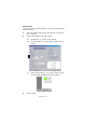
PRINTING PAGES The whole manual, individual pages, or sections may be printed. The procedure is: 1. From the toolbar, select [File], then [Print] (or press the Ctrl + P keys). 2. Choose which pages you wish to print: (a) [All pages], (1), for the entire manual. (b) [Current page], (2), for the page at which you are looking. 1 2 3 (c) 3. [Pages from] and [to], (3), for the range of pages you specify by entering their page numbers. Click on [OK].
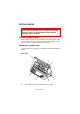
GETTING STARTED WARNING! If you have not already done so, familiarise yourself with the content of the Installation Safety booklet supplied with your printer. RETAINING PACKING MATERIALS After setting up your printer according to the instructions in the Set-up Guide, retain your packing materials and container in case you ever need to ship or transport your printer. IDENTIFYING COMPONENT PARTS The main parts of your printer are identified and briefly explained below. FRONT VIEW 10 1 2 3 9 8 7 4 6 1.
2. Top Cover: open and close for access, for example when changing a ribbon cartridge. Keep closed for noise reduction. 3. Control Panel: contains button switches and indicators (described in detail later) that allow you to operate the printer. 4. Power Switch: to turn the printer power ON/OFF. 5. Platen Knob: turn to move or eject the paper. 6. Paper Tray: to hold cut sheet paper for use by the printer (one sheet at a time). 7.
REAR VIEW 1 2 6 3 5 4 1. Optional connector position: connect to optional accessory serial interface card or 100BASE-TX/10BASE-T network card. 2. USB connector: connect to USB interface cable. 3. Parallel connector: connect to parallel interface connector. 4. Pin Tractor: to load and feed continuous forms. 5. Power connector: connect to printer power cable. 6. Rear Cover: open and close for access, for example when loading continuous forms.
LOCATING YOUR PRINTER > Select a firm, solid surface on which to site your printer. > Allow enough space around your printer (e.g. at least 60 cm from any wall) for easy access to the Platen Knob and the various paper feed paths. >=60 cm 75 cm > Make sure a grounded power outlet is available nearby.
POWERING ON YOUR PRINTER 1. Ensure that your printer Power Switch is set to OFF. 2. Connect the power cable connector (1) to the power connector (2) on the printer. 1 2 3. Connect the power cable to a 220/240 V AC power outlet and switch on the outlet power. 4. Turn the printer Power Switch to ON. 5. Check that the POWER indicator on the control panel illuminates.
PRODUCING A TEST PRINT To check that your printer is operational, produce a test print on a sheet of 80 gsm A4 paper (for example) as follows: CAUTION! Allow at least 5 seconds between turning the printer ON after turning it OFF. A shorter time interval between turning ON/OFF operations may cause printer power failure. Do not turn the printer OFF while it is printing as this may result in damage to the print head. 1. Turn the printer Power Switch to OFF. 2.
CONNECTING TO A COMPUTER In this section you will interconnect your printer and computer, install the printer driver in your computer and print a test page. INTERCONNECTING PRINTER AND COMPUTER INTERFACES Your printer is equipped with two data interfaces: CAUTION! Do not use both parallel and USB printing together. > Parallel: for direct connection to a PC. This port requires a bi-directional (IEEE 1284 compliant) parallel cable. > USB: for connection to a PC running Windows 98 or above.
INTERCONNECTION 1. Ensure that both printer and computer are turned OFF. 2. Connect the required interface cable, USB (1) or parallel (2), to the printer and then to the computer (3). 1 2 1 3 3 3. 2 Turn ON the printer and then turn ON the computer. INSTALLING THE PRINTER DRIVER Insert the Drivers CD into your computer and follow the onscreen instructions to install the printer driver for use with your printer. PRINTING A TEST PAGE As an example, using Windows XP: 1.
PRINTING FROM A COMPUTER When printing to your printer from, for example, a Windows application on your computer, make your printing selections from the driver windows that appear on screen. These driver windows have been designed to be easy to use and intuitive while supplementary on-line help is available by clicking each window Help button .
PAPER HANDLING This section describes how to use cut sheet paper and continuous forms in your printer. LOADING CUT SHEET PAPER 1. Ensure that the printer is turned ON. NOTE If there are any continuous forms in the printer, eject them as described in “Removing continuous forms” on page 25. 2. Ensure that the Pin Tractor covers (1) are closed to avoid the possibility of paper jams. 1 1 3. Ensure the Paper Type Lever (1) is set to Cut Sheet.
4. Set the left margin of the paper by adjusting the Paper Guide (1) along the scale (2) relative to the start of printed line marker arrow (3). 4 2 1 5. 3 Adjust the Paper Thickness Lever (4) to suit the paper. See “Setting the Paper Thickness lever” on page 26. NOTE If the Paper Thickness Lever setting does not match the paper being used, paper feeding and printing may not work properly. 6.
NOTE Ensure that the paper is accurately aligned along the Paper Guide to avoid the possibility of skew printing. When printing an envelope, do not fold up the flap. A flap aligned along the Paper Guide can lead to skew printing. EJECTING CUT SHEET PAPER When the printer reaches the end of the cut sheet page it automatically ejects the page. If required, add another sheet for the printer to continue printing from where it left off. To eject a cut sheet left in the printer, carry out the following: 1.
2. Position the continuous forms supply directly below the printer, no more than 3 cm left or right of the printer paper path. 3. Ensure the rear of the printer is close to and parallel with the edge of the surface and at least 60 cm from any wall. FEEDING CONTINUOUS FORMS 1. Ensure that the printer is turned ON. NOTE If there is a cut sheet in the printer, eject it as described in “Ejecting cut sheet paper” on page 20. 2. Ensure the Paper Type Lever (1) is set to Continuous Forms. 1 3.
5. Lift the locking lever (1) of the left Pin Tractor and slide the Pin Tractor as required to adjust the paper position relative to the first horizontal character centre mark (2). 1 2 Press the locking lever back down to lock the Pin Tractor in the desired position. 6. Lift the locking lever (1) of the right Pin Tractor and slide the Pin Tractor to the required position to accommodate the width of the continuous forms to be used.
7. Open the left and right Pin Tractor covers (1) and feed the continuous forms in the direction of the arrows, locating the sprocket holes (2) in the forms onto the sprocket pins. Ensure that the forms are properly aligned on the sprocket pins (3), then close the covers. 1 2 3 8. Adjust the right Pin Tractor (1) to accommodate the width of the continuous forms, taking care that the forms are held neither too loosely nor too tightly between the Pin Tractors.
10. Press the FF/LOAD button. The continuous forms will be taken into the printer and positioned at the first line print position and the SEL indicator will illuminate. TEARING OFF CONTINUOUS FORMS 1. With the SEL indicator illuminated, press the TEAR button to eject the continuous forms onto the Paper Tray. 2. Carefully tear off the forms along the tear-off perforations in the direction shown. Using excessive force may result in tearing at a position other than the tear-off perforations. 3.
2. Check the position of the tear-off perforations (1) relative to the paper cutter (2). (Paper Tray (3) is shown for clarity.) 2 3 1 (a) To advance the forms, hold down the TEAR button and press the FF/LOAD button. (b) To retract the forms, hold down the TEAR button and press the LF button. NOTE If a movement greater than +- 7/90 in is specified, the QUIET indicator blinks and the above adjustment cannot be made. 3.
4. Open the Rear Cover by gently pulling it out horizontally to the end of its travel then swinging it upwards until it locks into position. 5. Lift the Pin Tractor covers (1) and remove the forms. 1 6. Close the Pin Tractor covers. 7. Close the Rear Cover by gently swinging it downwards to the horizontal and then pushing it inwards until it locks into position.
LEVER POSITION PAPER TYPE 1 2 3 4 part X 5 part X 6 part 4 5-9 X Set the Paper Thickness lever for overall paper thickness as follows: OVERALL PAPER THICKNESS LEVER POSITION 0.06 – 0.12 mm 1 0.13 – 0.21 mm 2 0.22 – 0.30 mm 3 0.31 – 0.39 mm 4 0.40 – 0.48 mm 5 0.49 – 0.57 mm 6 0.58 – 0.66 mm 7 0.67 – 0.75 mm 8 0.76 – 0.84 mm 9 NOTE Printing with lever positions 5 – 9 is not guaranteed.
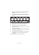
OPERATING INSTRUCTIONS CONTROL PANEL The status/alarm indicators and button switches on the control panel allow you to check printer status and control the printer.
INDICATORS INDICATOR STATUS MEANING SEL ON Printer is on-line i.e. is available to print OFF Printer is off-line i.e. is not available to print Flashing When flashing together with the ALARM indicator, printing cannot be resumed at this stage. Turn the power OFF, verify that the carriage moves properly, then turn the power ON again. If the problem is still there after you turn the power ON again, contact your dealer. ALARM ON Paper end status i.e.
BUTTON SWITCHES SWITCH STATUS FUNCTION SEL On-line Sets the printer to off-line Off-line Sets the printer to on-line and disalarms the printer SHIFT LF FF/LOAD TEAR PARK Used only in conjunction with one of the following buttons: SEL, LF, FF/LOAD, PARK, TEAR described below. On-line Feeds paper by one line. Holding the button down results in continuous line feeding. Off-line Feeds paper by one line. Holding the button down results in continuous line feeding.
SWITCH STATUS SHIFT+LF FUNCTION Microfeed (0.14 mm step) down Hold this button combination down for continuous feeding or ejecting of paper. SHIFT+FF/LOAD Microfeed (0.14 mm step) up Hold this button combination down for continuous feeding or ejecting of paper. SHIFT+PARK SHIFT+TEAR On-line Ineffective Off-line Saves the set paper start position (first line print position).
SETTING MENU VALUES The following information explains the printer settings and how you can change them. Printer items and their values are printed for reference. CONFIRMING CURRENT SETTINGS To print the current menu settings, use a cut sheet of A4 paper or continuous forms of width at least 254 mm. In this example, a sheet of A4 paper is used. 1. Set the Paper Type lever to cut sheet mode. 2.
MENU SETTING NOTE Before changing menu settings, you may wish to print the current menu settings as in “Confirming current settings” on page 32. Set menu item values (printed out for reference as you proceed) as follows: 1. Press LF (or SHIFT and LF together) to step forward (backward) through the menu items to the required item. 2. To change the setting for a selected item, press FF/LOAD (or SHIFT and FF/LOAD together) to step forward (backward) through the setting values to the required setting. 3.
ITEM FUNCTION SETTING Proportional Spacing Select whether to use proportional spacing or not. Yes No Style Select either font style. Normal, Italics Size Select the character scale size. Single, Double Character Set Select either ANK character code table. Set I Set II Language Set Select a language character set.
ITEM FUNCTION SETTING Code Page Select a code page.
ITEM FUNCTION SETTING Rcv Buffer Select size of the received buffer. 0, 2 K, 32 K, 64 K Print Suppress Effective Set whether to enable or disable a print suppress setup command. Yes No Auto LF Select whether to perform auto LF operation or not upon receiving a CR code. Yes No Auto CR *IBM PPR only Select whether to perform auto CR operation upon receiving a carriage return command. Yes No SI Select Pitch (10CPI) *IBM PPR/AGM only Set how to handle an SI command received in 10 CPI mode.
ITEM FUNCTION SETTING PE Detection Select whether to detect paper end or not. OFF ON Table Print Set whether to divide a path or not to print on occasions when printing by the same headpin continues for 3 in or more in the same print block. Standard Special Line Spacing Select line feed pitch. 6 LPI 8 LPI Page Width Set width of a line to determine the number of ANK (10CPI) characters to be printed. With this setting, the right margin is set.
ITEM FUNCTION SETTING TOF (Continuous) Select the reference position for the TOF position when auto loading continuous form paper from the rear of the printer. (Up to the mid-section of characters in the first line.) “1Chr. Set Pos.” is printed if the TOF position is set by using SHIFT + PARK switches. 2.12 mm (1/12 in) 4.23 mm (1/6 in) 6.35 mm (1/4 in) 8.47 mm (1/3 in) 10.58 mm (5/12 in) 12.7 mm (1/2 in) 14.82 mm (7/12 in) 16.93 mm (2/3 in) 19.05 mm (3/4 in) 21.17 mm (5/6 in) 23.28 mm (11/12 in) 25.
ITEM FUNCTION SETTING Wait Time Select the waiting time between setting paper on the tray and feeding it while the printer is waiting for paper to be fed in cut-paper manual feed mode. 500 ms 1 sec 2 sec I-Prime Select whether to print or clear buffer contents upon initialisation by receiving I-PRIME. Invalid Buffer Clear Buffer Print Auto Feed XT *EPSON only Set the validity of an Auto Feed XT signal.
ITEM FUNCTION SETTING Registration Low Adjust the print starting position on printing in the reverse direction. (The position moves to the right or left in 1/ 720 in increments.) -10 – -1 0 +10 – +1 Registration Normal Adjust the print starting position on printing in the reverse direction. (The position moves to the right or left in 1/ 720 in increments.) -10 – -1 0 +10 – +1 Registration High1 Adjust the print starting position on printing in the reverse direction.
ADJUSTING TOF POSITION Use the following procedure to set TOF to accord with the reference position (6.35 mm (0.25 in)). The reference position refers to the first line of the paper i.e. the position to which the printer feeds the paper when automatically loading the paper. NOTE Adjusting of TOF can be done in cut sheet mode or continuous forms mode. 1.
set the printer off-line and press and hold down the SHIFT and PARK buttons for 3 seconds. NOTE Do not turn the Platen Knob or switch off the printer during the above procedure. QUICK PRINTER SETTINGS PRINTER IMPACT MODE When switched ON, the printer enters the impact mode selected in the menu. You can change this to normal speed and quiet printing without using the menus as follows. Normal speed printing Use this for standard file printing operations. 1. Ensure the SEL indicator is illuminated. 2.
NOTE If the paper on top is so thick that duplication on the paper below it fails, use emphasis printing. In emphasis printing mode, printing is carried out twice. The print may become blurred if high density characters and graphics are printed using a new ribbon. In emphasis mode, ensure that the paper is flat to avoid possible printing errors.
TROUBLESHOOTING CLEARING PAPER JAMS CUT SHEET PAPER JAMMED IN PRINTER WARNING! Do not carry out any operations inside the printer with the Power Switch set to ON. 1. Set the Power Switch to OFF. 2. Open the Top Cover. 3. Set the Paper Thickness lever to the Replace Ribbon position (position 10). WARNING! The Print Head may be hot after printing. Allow it to cool before touching it.
4. Move the Print Head away from the paper. 5. Rotate the Platen Knob in the relevant direction and pull the cut sheet out from the front or rear of the printer. 6. If a paper fragment remains inside the printer: (a) use forceps to grip and extract it or (b) insert a triple folded sheet from the Paper Tray and turn the Platen Knob to pass the folded sheet through and push out the paper fragment. 7. When the paper jams are cleared, close the printer Top Cover. 8. Set the Power Switch to ON.
CONTINUOUS FORMS JAMMED IN PRINTER WARNING! Do not carry out any operations inside the printer with the Power Switch set to ON. 1. Set the Power Switch to OFF. 2. Tear off any unprinted continuous forms. 3. Open the Rear Cover by gently pulling it out horizontally to the end of its travel then swinging it upwards until it locks into position. 4. Raise each Pin Tractor cover (1) and remove the continuous forms from the Pin Tractors. 1 5.
RESPONDING TO ALARM CONDITIONS Use the following table for guidance on how to respond to indicated alarm conditions. INDICATOR ALARM MEANINGS AND ACTIONS SEL ALARM OFF ON Paper has run out. Add paper and press the SEL button. OFF Flashing The Paper Type lever is wrongly set for the type of paper in use. Press the SEL button and set the Paper Type lever to the correct position. OFF Flashing Problem with cut sheet feeding. Remove the cut sheet.
RESPONDING TO GENERAL PROBLEMS Use the following table to help you to identify symptoms with possible causes and take suggested remedial actions. PROBLEM CAUSE ACTION The power cable is not properly connected. Check the power cable is properly connected at both power outlet and printer. Power outlet problem or power outage. Plug another appliance into this outlet to check if it works. The printer driver is not installed properly. Re-install the printer driver correctly.
PROBLEM CAUSE ACTION When the print head overheats, the printer automatically starts unidirectional split printing. When the print head temperature drops sufficiently, the printer will return to its original operation. There is contamination on the carriage shaft. Clean any paper dust and contamination from the carriage with a dry cloth. The Paper Thickness lever position does not match the paper. Correct the Paper Thickness lever setting. The printer is set to print at high speed.
PROBLEM CAUSE ACTION The printout differs from the screen display. Printout of completely different characters or symbols. Too high or too low TOF (where printing starts). Incorrect print setup for the user application. Reselect print setup for the applications according to priority. The application control codes for the previous print operation are still enabled. Initialise the printer. The input application control signal is not correct. Print in hex dump mode and verify the data content.
PROBLEM CAUSE ACTION When cut sheets are used, the content of a single sheet is printed on two sheets. The paper setting selected in the application does not match the physical paper size. Match the paper setting selected in the application with the physical paper in use. It does not match the lines per page as the printer automatically detected. Leave enough top and bottom margin in the application. Correct the cut sheet LF adjustment. The content of a single line is printed in two lines.
PROBLEM CAUSE ACTION The platen rotates without paper feed, or continuous forms instead of cut sheets are fed. Sheets are not loaded to the end. Load sheets to the end. The printer is in the continuous forms mode. Eject the continuous forms and select cut sheet mode for the printer. Paper distortion. Sheets are not loaded to the end, or they are not inserted straight. Load sheets to the end. Paper with wrinkles, folds or other defects. Change paper. Paper not specified for the printer.
PROBLEM CAUSE ACTION The selected skip over perforation spacing does not match the physical tear-off perforation positions. The paper length selected in the application does not match the physical paper length. Match the paper length selected in the application with the physical paper length in use. Select the paper length in number of lines in the application. Abnormal switchover between cut sheet and continuous forms modes. No cut sheet feed. The printer is in continuous forms mode.
CLEANING YOUR PRINTER To keep your printer in good operating condition, you are advised to clean it regularly. WARNING! Set the printer Power Switch to OFF and disconnect the power cable from the printer before cleaning the printer. PRINTER EXTERIOR CAUTION! Keep the Top Cover closed to avoid the possibility of detergent entering the printer Clean the exterior of the printer as required, but at least every six months or 300 hours of operation, whichever comes first. 1.
Using a soft cloth, cotton swabs and a vacuum cleaner, clean the interior of the printer as follows: 1 2 WHERE TO CLEAN WHAT TO CLEAN The carriage (1) and the area around it Clean and remove paper waste, dirt, dust and ribbon shreds. The paper travel surface (2) CAUTION! When you clean the interior of the printer with a vacuum cleaner, do not attempt to clean any parts smaller than the suction nozzle.
CONSUMABLES AND ACCESSORIES CONSUMABLES When the printed image becomes faint or incomplete, replace the ribbon cartridge. CHANGING A RIBBON CARTRIDGE CAUTION! Only use genuine Oki Original consumables to ensure the best quality and performance from your hardware. Non-Oki Original products may damage your printer’s performance and invalidate your warranty. WARNING! Do not change the ribbon cartridge with the Power Switch set to ON. 1. Set the Power Switch to OFF. 2.
3. Move the carriage (1) to the cutout (2) for ribbon replacement position. 1 4. 2 Hold the ribbon cartridge (1) with your fingers pressing on its ribbon guide (2) and slope it up and out to remove it from the carriage.
5. Holding the ribbon cartridge (1) close to both ends, slope it up and out until it unlocks then remove it along the direction indicated by the arrows. 1 6. Dispose of the cartridge in accordance with your local guidelines. 7. Remove the new ribbon cartridge from its wrapping and note the position of the Ribbon Guide (1), Knob (2) and Pin (3).
8. In the direction indicated by the arrows, insert the pins at both ends of the ribbon cartridge (1) into the U grooves (2) in the printer until the ribbon cartridge is fully locked. NOTE It may be easier to mount the ribbon cartridge in place if you align it with the topside of the grooves. Also, a slightly loose ribbon may make it easier to mount the ribbon cartridge. 2 1 9.
10. Turn the knob (1) clockwise (in the direction of the arrow) to wind up the ribbon. CAUTION! Do not turn the knob anticlockwise as the ribbon might jam. Make sure that the ribbon is not twisted or damaged when it goes through the gap between the Print Head and the ribbon guide. 1 11. Close the printer Top Cover. 12. Set the Paper Thickness lever to match the paper being used. (See “Setting the Paper Thickness lever” on page 26.) 13. Set the printer Power Switch to ON.
CONSUMABLE ORDER INFORMATION ITEM LIFE ORDER NO. Ribbon cartridge (Black) 4 million characters 43503601 ACCESSORIES The following accessories are available for your printer: > RS-232C Serial Interface > OL7120e 100BASE-TX/10BASE-T Network Interface Installation instructions are supplied with the accessories. The Network Configuration Guide on the CD that accompanies the Network Interface card provides detailed configuration information for the OL7120e. ACCESSORY ORDER INFORMATION ITEM ORDER NO.
SPECIFICATIONS ITEM SPECIFICATION Model No. D21008B (ML6300FB) Print method Impact dot matrix Print head 24 pins, 0.2 mm (0.0079 in) diameter Print direction Bi-directional, short-line-seeking printing Print speed High Speed Draft (HSD) Letter Quality (LQ) Utility 400cps @ 10 cpi 100 cps @ 10 cpi 300 cps @ 10 cpi Line Feed (LF) time Approximately 65 ms per line for LF of 4.23 mm (1/6 in) Form Feed (FF) speed Approximately 114.3 mm/s (4.
ITEM SPECIFICATION Cut-sheet paper Paper width Paper length Single-part Weight Multipart Weight Number of copies Thickness 90 to 304.8 mm (3.54 to 12 in) 70 to 364 mm (2.76 to 14.33 in) 52 to 209 gsm 40 gsm standard Original plus 5 copies 0.36 mm (0.014 in) maximum Continuous Paper Paper width Paper length Single-part Weight Pressure-sensitive Weight Number of copies Thickness Multipart-carbon-lined or multipart-interleaf Weight Number of copies Thickness 76.2 to 304.8 mm (3 to 12 in) 76.2 to 355.
ITEM SPECIFICATION Dust and corrosion Use the printer in a general office environment. Environmental conditions Operating 5°C – 40°C, 30% – 85% RH (Testing condition for print precision: 15°C – 30°C, 40% – 70%RH) Storage -20°C – 60°C, 0% – 95% RH When the printer is stored, it should be in its original packaging, with no moisture formation.
APPENDIX A – REAR COVER REMOVAL If required, the Rear Cover can be removed and refitted as described below. CAUTION! When removing or refitting the Rear Cover, take care not to apply excessive force. REMOVAL 1.
REFITTING 1.
INDEX A P accessories list ......................................... ordering.................................. alarm indications .......................... aligning perforations ..................... 61 61 47 24 B button switches ............................ 30 C cleaning exterior .................................. 54 interior ................................... 54 D drivers ........................................ 16 E ejecting paper continuous forms ..................... 24 cut sheet .............
OKI PRINTING SOLUTIONS CONTACT DETAILS Oki Systems (UK) Limited 550 Dundee Road Slough Trading Estate Slough, SL1 4LE Tel:44 (0) 1753 819819 Fax:44 (0) 1753 819899 http://www.oki.co.uk Oki Systems Ireland Limited The Square Industrial Complex Tallaght, Dublin 24, Ireland Tel:+353 1 4049590 Fax:+353 1 4049591 http://www.oki.ie Technical Support: Tel:+353 1 4049570 Fax:+353 1 4049555 E-mail: tech.support@oki.ie OKI Systems (Ireland) Ltd.
Oki Europe Limited Central House Balfour Road Hounslow TW3 1HY United Kingdom Tel: +44 (0) 208 219 2190 Fax: +44 (0) 208 219 2199 www.okiprintingsolutions.