OKIPAGE24DX / OKIPAGE24dx LED Page Printer Maintenance Manual ODA/ OEL/ INT 1998.12.
PREFACE This maintenance manual describes the field maintenance methods for OKIPAGE24DX/OKIPAGE24dx. This manual is written for use by maintenance personnel. Note, however, that the user should refer to the USER’S MANUAL for methods of handling and operating the equipment.
CONTENTS 1. CONFIGURATION ....................................................................................... 7 1.1 1.2 1.3 1.4 1.5 System Configuration ................................................................................................. Printer Configuration .................................................................................................. Optional Configuration ............................................................................................... Specification ..
3.3.27 3.3.28 3.3.29 3.3.30 3.3.31 3.3.32 3.3.33 3.3.34 3.3.35 3.3.36 Power supply unit ......................................................................................... Lever-Paper end & Lever-Paper near end ................................................... Guide Assy-Cassette (L) .............................................................................. Guide Assy-Cassette (R) .............................................................................. Removing/Installing Duplex Unit ....
APPENDIX A CENTRONICS PARALLEL INTERFACE .................................... 185 APPENDIX B RS-232C SERIAL INTERFACE ................................................... 189 APPENDIX C SECOND/ THIRD PAPER FEEDER MAINTENANCE ................. 191 1. OUTLINE ................................................................................................................... 191 1.1 1.2 2. Description of operartion .........................................................................................
3.3 4. Precautions Prior to the Troubleshooting ..................................................... Preparations for the Troubleshooting ........................................................... Troubleshooting Method ............................................................................... 4.3.1 LCD Status Message List ................................................................ 4.3.2 Troubleshooting Flow ......................................................................
1. CONFIGURATION 1.1 System Configuration OKIPAGE24DX / OKIPAGE24dx consists of control and engine blocks as the standard configuration (See Figure 1-1.) In addition, the following options are also available. AC IN 120V 230V Printer Operator panel PC etc. Face up stacker Face down stacker Power supply unit Main control Printer Mechanism * I/D unit Centronics Parallel interface (Bidirection) * DC Fan Toner Cartridge Front Feeder LED head Motor-Main Hopping motor RS-232C Serial I/F LAN etc.
1.2 Printer Configuration The printer unit consists of the following hardware components: • Electro-photographic processor • Paper feeder • Controller • Operator panel • Power supply unit • Duplex Unit Figure 1-2 shows the printer unit configuration.
1.3 Optional Configuration The options below are available for use with OKIPAGE24DX / OKIPAGE24dx. They are sold separately from the printer unit. (1) Multi Feeder (2) Second/ Third Paper Feeder (3) D-RAM SIMM module (72 pin SIMM, 16 MB/32 MB, EDO SIMM type) See 7.2 (1) for where to install.
(4) Flash ROM module (72 pin SIMM, 4MB/8MB) See 7.2 (1) for where to install.
1.4 Specification (1) Type Desk top (2) External dimensions (excludes protruding Portion) Height 13.0” Width 14.4” Depth 18.2” (3) Weight 21.
(12) Temperature and humidity In operation Power off mode During Storage Unit 50 - 90 (10 - 32) 32 - 110 (0 - 43) 14 - 110 (–10 - 43) °F (°C) 20 - 80 10 - 90 10 - 90 %RH Maximum wet bulb temperature 77 (25) 80.4 (26.8) °F (°C) Minimum difference of wet and dry bulb temperatures 35.6 35.6 °F (2) (2) (°C) Temperature Humidity Notes: 1. Storage conditions specified above apply to printers in packed condition. 2. Temperature and humidity must be in the range where no condensation occurs.
1.5 Safety Standards 1.5.1 Certification label The safety certification label is affixed to the printer in the position below. ex. ODA 120V 1.5.2 Warning label The warning label is affixed to the portion which may cause an injury to human body. Follow the instructions on warning labels during maintenance.
2. OPERATION DESCRIPTION OKIPAGE24DX / OKIPAGE24dx consists of a main control board, a power supply unit (120V/ 230V), a power supply unit (high voltage), an operator panel and an electro-photographic process mechanism. The control board receives data through a host I/F, decodes and edits the data, and stores the edited data in a memory. After completing edition of one page of data, it references the font memory and generates bit data on the same memory.
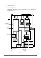
MAIN BOARD (BOARD-FFF) FLASH ROM Module DUPLEX unit PS ROM MULTI feeder 2nd tray PCL ROM 3rd tray Paper end sensor Extension DRAM Module Paper near end sensor LSI Centronics I/F TRANSISTOR CL Clutch for Regist Roller TRANSISTOR CL Clutch for Hopping Roller DRIVER M Hopping Motor DRIVER M Main Motor Driver Receiver RS232C I/F Driver Receiver CPU OKI HSP I/F Board (Option) LAN etc.
2.1 Main Control Board (BOARD-FFF) The control board consists of an one chip CPU,a LSI, program/font ROM's, DRAM's, an EEPROM, a host interface circuit, and a mechanism driving circuit. (1) One-chip CPU The one-chip CPU is a custom CPU (32-bit internal bus, 32-bit external bus, 120-MHz clock) that incorporates an RISC CPU and its peripheral devices, and has the following functions.
(3) DRAM's 16-Megabyte DRAM (64 Mbit DRAM x 2) is mounted as resident memory to be used for storing the program and providing various buffers. This DRAM is expandable up to 128 Mbytes by adding expansion memory (SIMMs). This DRAM provides the areas shown in the following table.
(a) Centronics bidirectional parallel interface This is an interface conforming to IEEE-1284 and provides either of unidirectional and bidirectional communications according to each of the following communication modes. • Compatibility mode Unidirectional communications from the host to the printer. • Nibble mode This mode transmits 4-bit wide data from the printer to the host. In this mode, each 1-byte data is transferred in the form of two nibbles using ERROR, BUSY, FAULT, and SELECT signal leads.
(7) RAM module • Pin layout 1 • 36 37 72 Basic specificaton - Type: 72 pins Standerd SIMM (32 bits buss width) [Note : EDO SIMMtype] - Access time: 60ns, 70ns, 80ns, 100ns - Capacity: 16 or 32MB - Parity: None (8) Flash ROM module • Pin layout Board-FSL or Board-FSL-2 (8MB) (4MB) 1 • 36 37 72 Basic specificaton - Type: 72 pins SIIM (32 bits buss width) - Access time: 90ns - Capacity: 4 or 8MB 40930701TH DRAFT Vesion 19 /
2.2 Power Supply Unit The power supply unit consists of an AC filter circuit, a low voltage power supply circuit, a high voltage power supply circuit, heater drive circuit, and photosensors. (1) Low voltage power supply circuit This circuit generates the following voltages. Output voltage Use +5 V Logic circuit supply voltage +30 V Motor and fan drive voltage and source voltage for high-voltage supply +8 V Reset circuit, RS232C Line voltage –8 V RS232C Line voltage +3.
Figure 2-3 shows the sensor layout diagram. Paper running direction Roller-exit Roller-feeder (c) Outlet sensor Roller-Heat Roller-transfer Paper sensor Toner sensor Roller-regist Inlet sensor 1 Inlet sensor 2 Feed roller Figure 2-3 Sensor Function Sensing state Inlet sensor 1 Detects the leading part of the paper and gives the supervision timing for switching from hopping operation to feeding operation.
2.3 Electro-photographic Process 2.3.1 Electro-photographic process mechanism This mechanism prints image data from the control board on the paper by electro-photographic process. The Figure 2-4 shows the layout of the electro-photographic process mechanism.
(1) Image drum unit The image drum unit consists of a sensitive drum, a charger, and a developer. The unit forms a toner image on the sensitive drum, using a electrostatic latent image formed by the LED head. (2) Hopping motor This motor is a pulse motor of 48 steps/rotation that is two-phase excited by the signal from the control board. It drives the hopping roller of the first tray and the front feed roller via two one-way clutches according to the direction of rotation.
2.3.2 Electro-photographic process The electro-photographic processing is outlined below. Figure 2-5 shows the electro-photographic printing process. 1 Charging The surface of the image drum is uniformly charged with negative charges by applying a negative voltage to the charge roller. 2 Exposure Light emitted from the LED head irradiates the negatively charged surface of the image drum.
Figure 2-5 40930701TH DRAFT Vesion 25 / (Face up) Paper eject Paper eject roller Paper eject Cleaning Fusing pressure Cleaning roller Fusing Fusing Heater roller Outlet sensor Paper path selector Power supply Charger roller Power supply (Face down) Paper eject Paper eject roller Power supply Image production developing Paper feed Registration roller Transfer roller Developing roller Paper registration Paper sensor Developing Power supply (Bias voltage) Transfer Transfer Clea
40930701TH DRAFT Vesion Figure 2-6 DMON-N (DRUM MOTOR) OFF ON HMON-N (HOPPING MOTOR) OFF ON PWM1-P (CLUCH for hopping) ON OFF PWM2-P (CLUCH for REGISTRATION) ON OFF PSIN1-N (INLETSENSOR1) OFF ON WRSENSE-N (PAPER SENSOR) OFF ON PSOUT-N (OUTLET SENSOR) OFF ON STB-N (LED HEAD) OFF ON PAPER PAPER TRAY PRINTER SIMPLEX PRINTING TIMING CHART STACKER 26 /
40930701TH DRAFT Vesion Figure 2-7 DMON-N (DRUM MOTOR) OFF ON HMON-N (HOPPING MOTOR) OFF ON PWM1-P CLUCH for hopping) ON OFF PWM2-P (CLUCH for REGISTRATION) ON OFF PSIN1-N (INLETSENSOR1) OFF ON WRSENSE-N (PAPER SENSOR) OFF ON PSOUT-N (OUTLET SENSOR) OFF ON STB-N (LED HEAD) OFF ON DUPMON-N (MAIN MOTOR in DUPLEX UNIT) OFF ON CLON-P (CLUCH in DUPLEX UNIT) ON OFF SLON-P (SOLENOID in DUPLEX UNIT) ON OFF DUPINSNS-N (INLET SENSOR in DUPLEX UNIT) OFF ON OFF DUPRSNS-N (REAR SENSOR inDUPLEX
2.4.3 Process operation descriptions (1) Hopping Hoppings from the first tray and the front feeder are effected by a single hopping motor in the mechanism shown below. Hopping Motor Front Feeder Duplex Unit 1st Tray Turning the Hopping motor in direction a (CW) drives the 1st Hopping Roller. Turning the Hopping motor in direction b (CCW) drives the Front Hopping Roller.
(a) Hopping from the 1st Tray 1 Hopping Rotating the Hopping Motor in direction a (CW) drives the 1st Hopping Roller and the Sub Roller then pick up a sheet of paper in the 1st tray. The Main Motor is always driven in direction c (CCW) on printing. After the paper fed approx. 30mm from the tray, the Clutch (Feed) drives the Align Roller to advance the paper until the Inlet Sensor turns on.
(b) Hopping from the Front Feeder 1 Hopping The Front Feeder Plate is normally locked at the lower position by the Release Lever and turn the Micro SW on. Top of the FF Cam which attached on end of the Front Hopping Shaft is normally located Upper position (0 to 30 degree : home position). Rotating the Hopping Motor in direction b (CCW) drives the Front Hopping Shaft and then attached the FF Cam and the Front Hopping Roller are driven. During the FF Cam rotated approx.
Hopping Motor Hopping Roller (Front Feeder) Gear C (one way clutch build in) b (CCW) Pressure Roller Front Feeder Plate Inlet Sensor Paper Regist Roller Paper d Gear A Hopping Roller 1st Hopping Gear (One way Gear build in) Sub Roller (home position) 0~30° Release Lever Front Hopping Shaft 60° 180° FF Cam Micro SW Front Feeder Plate 40930701TH DRAFT Vesion 31 /
Pressure Roller Regist Roller Clutch (Regist) Write Sensor Inlet Sensor c Gear E Clutch (Feed) Gear D Main Motor Align Roller (2) Feeding After the end of hopping, the pulse motor dedicated for driving the registration roller rotates to drive the registration roller. The driven registration roller advances the paper until it comes out of the registration roller. When leading edge of the paper causes the paper sensor to turn on, the printing is started synchronously.
(3) Charging Charging is effected by applying a DC minus voltage to the charge roller that is in contact with the image drum surface. Power supply Charge roller Image drum (4) Exposure Light emitted from the LED head irradiates the image drum surface with negative charges. The surface potential of the irradiated part of the image drum drops, thereby forming an electrostatic latent image associated with the image signal.
(5) Developing Toner is attracted to the electrostatic latent image on the image drum surface to convert it into a visible toner image. Developing takes place at the contact between the image drum and the developing roller. 1 As the toner supply roller rotates while rubbing on the developing roller, a friction charge is generated between the developing roller and the toner, allowing the toner to be attracted to the developing roller.
(6) Transfer The transfer roller is composed of conductive sponge material and is designed to make the image drum surface and the paper closely into contact. Paper is placed over the image drum surface, and a positive charge, opposite in polarity to the toner, is applied to the paper from its reverse side.
(7) Fusing After the end of the transfer, the unfused toner image is fused on the paper under heat and pressure as it passes between the heater roller and the back-up roller. The heater roller with a Teflon coating incorporates a 750W heater (Halogen lamp), which heats the heat roller. A thermistor which is in contact with the heater roller regulates the heater roller at a predetermined temperature (about 180 ~ 200°C).
(8) Cleaning After the end of the transfer, residual toner on the image drum is attracted to the cleaning roller temporarily by static electricity to clean the image drum surface.
(10) Duplex unit When the Duplex Unit receives an instruction for both-sided printing from the unit, the separator will be opened by the action of a solenoid within Duplex and the route will be shifted to the one into the Duplex after one-sided printing of papers, which are fed from the tray, are completed. At this time, as the roller (1) rotates in the direction of arrow A, a sheet is retracted in the rear of the cassette.
2.3.4 Revision of LED Head Illumination An LED correcting head, which is capable of correcting the illumination of the LED for each dot, is being used in this printer. LED illumination correction function of 16 steps is carried out by using an EEPROM which is installed in the LSI that maintains the LED illumination correction values, and an LED correction drivers together as a pair. The LED correcting head consists of the correction control LSI , LED drivers , and an LED array.
930701TH DRAFT Vesion STRB4-N STRB3-N STRB2-N STRB1-N DATA 3~0 LOAD CLOCK RD Mode set Mode setting RD 1 0 0 0 8 clocks dummy cycle High-Z RD cycle 8 clocks RD cycle Correction data read correction data2 correction data1 Total 19992 clocks data4 data3 8 clocks 8 clocks Head data read RD cycle data2 data1 250ns min RD Mode enabled 8 clocks RD cycle correction data 4992 correction data 4991 High-Z (i) Read of correction data 40 /
40930701TH DRAFT Vesion STRB4~1 DATA 3~0 LOAD CLOCK 1 0 DIRECT 1 0 Correction data 4 Correction data 2 DIRECT Mode set Mode setting 0 Correction data 1 Correction data 3 Total 2496 clocks 250ns min DIRECT Mode enabled Correction data 4992 Correction data 4991 (ii) Transfer of correction data to head driver correction data 41 /
(2) One side wire-bonding head Correction Control LSI EEPROM LED Array LED From CPU DATA 3 DATA 2 DATA 1 DATA 0 CLOCK LOAD STRB4-N STRB3-N STRB2-N STRB1-N LED LED Driver LED LED LED LED LED LED Driver (i) LED head is set to the correction control read mode and all correction data stored in EEPROM within the correction control LSI are read by CPU, and stored temporarily in the memory.
40930701TH DRAFT Vesion STRB4-N STRB3-N STRB2-N STRB1-N DATA 3~0 LOAD CLOCK RD Mode set Mode setting RD 1 0 0 0 8 clocks dummy cycle High-Z RD cycle 8 clocks RD cycle Correction data read correction data2 correction data1 Total 20824 clocks data4 data3 8 clocks 8 clocks Head data read RD cycle data2 data1 250ns min RD Mode enabled 8 clocks RD cycle correction data 5200 correction data 5199 High-Z (i) Read of correction data 43 /
40930701TH DRAFT Vesion STRB4~1 DATA 3~0 LOAD CLOCK 1 0 DIRECT 1 STRB4-N STRB3-N STRB2-N STRB1-N 0 Tp Ditail figure A-D Mode setting 0 Tp A part of A more than 1µS Total 5200 clocks Tp Tp A part of B Tp Tp > 2µs Tp A part of C Tp Tp A part of D Tp Correction data1 Correction data1300 Correction data2600 Correction data3900 Correction data5200 Correction data2 Correction data1301 Correction data2601 Correction data3901 (ii) Transfer of correction data to head driver correction dat
The LED driver corrects the LED illumination by controlling the LED current. The LED illumination can be set in 16 steps, with 7 steps in the direction of illumination increase in relation to the standard value, and 8 steps in the direction of decrease. For this reason, the LED correction data is a 4-bit data for each dot. The relationship between the LED correction data and LED current correction steps with the LED driver used in an LED head is shown below.
The printing operation timing chart is shown below. Normal Mode Printing Timing Chart CLOCK LOAD DATA3~0 STRB1-N STRB2-N STRB3-N STRB4-N First line printing data sent Second line printing data sent First line printing The printing operation is carried out in normal mode. Under ordinary circumstances such as when the power is turned on or when LOAD signal level is low, the normal mode is enabled. The printing operation is carried out in the following sequence.
2.4 Paper Jam Detection The paper jam detection function supervises the paper state at power-on time and during printing. In the event that the following state occurs, this function interrupts the printing process. If any of the following errors is presented, recovery printing will be performed by removing the jammed paper (namely by opening the upper cover, removing the jammed paper and closing the upper cover).
2.5 Cover Open When the stacker cover is opened, the cover open microswitch on the Power Supply Unit (High voltage) is turned off to cut the supply of +30V to the high voltage power supply circuit. As a result, all high-voltage outputs are interrupted. At the same time, the CVOPN signal is sent to the control board to notify it of the off state of the microswitch, and the Main board performs the cover open processing.
2.6 Toner Low Detection • Composition The device consists of the stirring gear which rotates at a constant rate, the stirring bar and the magnet on the stirring bar. The stirring bar rotates through the link on the protrusion in the stirring gear. Magnet Protrusion Stirring Bar • Stirring Gear Operation Toner Low is detected by monitoring the time interval of the encounter of the magnet set on the sensor lever and the magnet on the stirring bar.
TONER FULL state TNRSNS t1 < 2.727/4 t1 2.727 SEC. TONER LOW state TNRSNS t1 t1 > 2.727/4 2.727 SEC. • When the toner low state is detected 2 times consecutively, Toner Low is established. • When the toner full state is detected 2 times consecutively, Toner Low is cancelled. • When there is no change with the toner sensor for 2 cycles (2.727 sec. x 2) or more, then the Toner Sensor Alarm is activated. • The toner sensor is not monitored while the drum motor is in halt.
2.7 Stacker-full Detection The sensor (interlocked with the lever) at the paper outlet to the stacker detects a stacker-full state (about 250 sheets) and stops printing of the ensuing pages. 2.8 Page Size Detection The four tab pieces are driven according to the setting position of the paper guide through the cam interlocked with the paper guide of the paper cassette.
3. PARTS REPLACEMENT The section explains the procedures for replacement of parts, assemblies, and units in the field. Only the removal procedures are explained here. Reverse the procedure for the installation. 3.1 Precautions for Parts Replacement (1) Before starting parts replacement, remove the AC cable and interface cable. (a) Remove the AC cable in the following procedure: i) Turn off ("o") the power switch of the printer ii) Disconnect the AC inlet plug of the AC cable from the AC receptacle.
[Service Tools] Table 3-1 shows the tools required for field replacement of printed circuit boards and units. Table 3-1 Service Tools No. Service Tools Q' ty Place of use 1 No. 1-100 Philips screwdriver 1 2~2.5 mm screws 2 No. 2-200 Philips screwdriver, Magnetized 1 3~5 mm screws 3 No. 3-100 screwdriver 1 4 No.
3.
Feed Unit-FRONT Toner Cartridge (Type 7) ID Unit (Type 7) HEAT-Assy ROLLER Assy-Feed Motor-Main FRAME-Main GUIDE-Assy-Eject LED HEAD DC Fan Motor Stacker Cover Figure 3-2 40930701TH DRAFT Vesion 55 /
Power Supply Unit (120V/230V) FRAME Assy-Hopping Power Supply Unit (High Voltage) ROLLER Assy-Feed FILM-Insulation Board PXC GUIDE Assy-Cassette(L) GUIDE Assy-Cassette(R) PLATE-Bottom Figure 3-3 40930701TH DRAFT Vesion 56 /
Photo sensor Solenoid Assy Control board (Board-LEX) Motor Connector (IMSA-9714N-14A) Photo sensor Figure 3-4 40930701TH DRAFT Vesion 57 /
40930701TH DRAFT Vesion (3.3.2) (3.3.4) (3.3.19) Contact Assy OP Panel Assy Paper Cassette, (3.3.10) Feeder Unit-Front Duplex Unit (3.3.31) (3.3.32) (3.3.33) Board-LEX Connector (3.3.34) (3.3.35) (3.3.36) Solemnoid Assy Motor (3.3.17) Photo Sensor Roller Assy-Feed TR Bearing Transfer Roller/TR Gear/ (3.3.21) (3.3.12) (3.3.11) (3.3.22) (3.3.13) (3.3.18) (3.3.9) (3.3.26) (3.3.27) Inlet Sensor Lever Power Supply Unit Paper near end (3.3.28) (3.3.
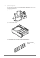
3.3.1 Face -up Stacker Assy (1) Turn off the AC Power Switch and unplug the AC Power Cord from the outlet. (2) Disconnect the Interface Cable 1. (3) Open the face-up stacker assy 2, unhook the right and left projections, and then remove the face-up stacker assy 2.
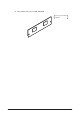
3.3.2 Contact Assy (1) Open the stacker assy 1 and unscrew 2 screw 2 to remove the assy -side (L)3. (2) Unscrew 2 screws 4 and remove the plate (contact) 5 and contact Assy 6. Note! Don’t deform the electrode plates of the contact assy 6.
3.3.3 DC Fan Motor (1) Remove the cover assy-side (L). [See 3.3.2 (1)] (2) Remove the DC fan motor 1 by pulling out the connector of DC fan motor 1.
3.3.4 OP Panel Assy (1) Disconnect the Interface cable 1. (2) Open the stacker assy 2, unscrew 2 screws 3 and remove the cover side (I/F) 4. (3) Remove 2 screws 5 and flexible cable 6 to remove the operator panel assy 7.
3.3.5 Board-FFF (1) Remove the operator panel assy and cover side (I/F). [See 3.3.4] (2) Unscrew 2 screws 1 and remove the cover side (R) 2. (3) Unscrew 16 screws 3 and remove plate-shield 4. (4) Unscrew 3 screws 5 and 2 screws 6, unplug all the connectors 7 , and remove Board-FFF 8.
3.3.6 Stacker Assy, Damper Arm, Cover Rear (1) Remove the face-up stacker assy. [See 3.3.1] (2) Remove the cover-side (L). [See 3.3.2 (1)] (3) Remove the OP panel assy. [See 3.3.4] (4) Remove the Board-FFF. [See 3.3.5] (5) Loosen 2 screws, unlock the both sides latches and remove the cover rear A. (6) Unscrew 2 screws 1 and cover frame 2. (7) Unscrew 3 screws 3 and remove the plate assy-side (R) 4.
3.3.7 Sensor Stacker Full (1) Turn the AC power switch off. Unplug the AC power cord from the outlet. (2) Remove the Stacker assy. [See 3.3.6] (3) Remove four screws 1. Remove stacker mount 2 by releasing the tabs at position 2A . (4) Remove Sensor stacker full 3 by releasing speading the plastic tabs on each side of sensor Assy 3 and lifting switch from cover.
3.3.8 Cable cover (guide film) (1) Turn the AC power switch off. Unplug the AC power cord from the outlet. (2) Remove the stacker Assy. [See 3.3.6] (3) Unscrew 2 screws 1 release tabs at portion 1A . Remove cable cover 2, guide film 3. 1A 2 1 3 Note: 40930701TH DRAFT Vesion Use care when replacing cable cover. Do not pitch, crimp, or cut cables or protective sheet.
3.3.9 Damper (1) Remove the damper arm. [See 3.3.6] (2) Unscrew 2 screws 1 and remove the two damper 2.
3.3.10 Feeder Unit-Front (1) Open the manual feed assy 1 and release both right and left parts by pulling out the engagements on the lower part. (2) Stand the manual feed assy 1 on end and unhook the engagements with both right and left manual feed hopper stays. (3) Remove the OP panel assy. [See 3.3.4] (4) Unscrew 5 screws 2 and remove the feeder unit-front 3.
3.3.11 Roller Assy-Regist (1) Remove the feeder unit-front. [See 3.3.10] (2) Remove an E-ring 3, gear assy-clutch 4, and four screws 1 in this order, and lifting out the roller assy-regist 2.
3.3.12 Motor -Main (1) Remove the stacker assy. [See 3.3.6] (2) Remove the feeder unit-front. [See 3.3.10] (At this point, the manual feed assy has not to be removed.) (3) Remove the DC fan motor. [See 3.3.3] (4) Remove the contact assy. [See 3.3.2] (5) Remove the plate-FG (F) 1. (6) Remove the TR gear 2 and roller transfer 3.(Use Holder-TR Eject F for the removal.) (7) Unscrew 7 screws 4 and remove the main frame 5.
F 2 3 8 Latch 5 View A 7 6 3 2 E 4 4 4 4 D B View A C D 0 9 A 4 4 1 5 40930701TH DRAFT Vesion 71 /
3.3.13 Guide Assy-Eject (1) Remove the lever back up release. [See 3.3.12(8)] (But the roller transfer/feeder unit front/plate-FG have not be removed) (2) Loosen 2 screws 1, unlock the both side’s latches and remove the cover rear 2. [See 3.3.6 (5)] (3) Unlock the latches on both sides of the guide assy-eject 3 and lifting it out.
3.3.14 Heat Assy (1) Remove the cover assy-side (L). [See 3.3.2 (1)] (2) Unplug the connectors 1, 2. (3) Unscrew 4 screws 3 and remove the heat assy 4 in the direction of the arrow by lifting the right side first. • As the heat assy 4 becomes high temperature soon after the power is turned off, start the work after it cools off sufficiently. • Carry out a reset of the counter after the replacement. (See Section 4.
3.3.15 Roller feed (C) (1) Remove the guide assy-eject. (See 3.3.13) (But roller transfer/feeder unit-front/plate-FG(F) have not be removed) (2) Remove the gear roller (C) 1 and bush 2, warp (a) part of the plate-FG (BK) 3. Take off the carrier bearing 4 and remove the roller feed (c) 5 in the direction of the arrow. Be careful not to deform (a) part of the plate-FG (BK) 3.
3.3.16 Roller Assy-BK (1) Remove the heat Assy. [See 3.3.14] (2) Remove the lever back up release. [See 3.3.12 (8)] (3) Unlock the engagement with the plate-FG (BK) 1 and lift out the roller heat assy 2.
3.3.17 Roller Assy-Feed (1) Remove the feeder unit -front. [See 3.3.10] (2) Remove the roller assy-feed 1 by unlocking a latch.
3.3.18 LED Head (1) Remove the stacker assy 1. [See 3.3.6] (2) Unplug the PC connector 2 and 2 LED cables 3 from the LED head 4. (3) Open the hooks of the cover stacker 1 in the direction of the arrow and remove the LED head 4. (4) Pull out the head spring 5 from the post. Note: Don't remove two LED cable 3 from the PC connector 2.
3.3.19 Paper cassette, ROLLER Ass-Feed, ROLLER-Assy-Hoppibg (1) Pull out the case assy -cassette 1 from the printer. (2) Remove the ROLLER Ass-Feed 2 and remove the ROLLER-Assy-Hopping 3.
3.3.20 Frame Assy-Separation (1) Turn the AC power switch off. Unplug the AC power cord from the outlet. (2) Pull out the case Assy-Cassette 1 from the printer.[See 3.3.19(1)] (3) Release two locks and remove frame assy-separation 2. (At this time, coil spring 3 is also remove. Be careful not to lose this spring.) 2 3 1 Insert 1 so as to pass the both arms of 1 behind two latches inside the alcove of 2 unit.
3.3.21 Transfer Roller/TR Gear/TR Bearing (1) Open the stacker cover . (2) Unlock the lock by lifting the TR gear 1 to remove the TR gear 1 and roller transfer 2. (Use the Holder-TR Eject 5 for the removal.) Note ! Don’t place the removed roller transfer directly on the desk and so on. When placing it, lay a paper and the like under it. (3) Remove right and left, 2 bearings 3 from the frame-main by sliding them inside while pushing them. At this time, 2 transfer springs R 4 would be detached simultaneously.
3.3.22 EP lock shaft (1) Turn the AC power switch off. Unplug the AC power cord from the outlet. (2) Remove Frame-Main [See.3.3.12(7)] (3) Remove screw 1. Turn EP lock lever (L) Assy 2 in the direction of arrow A . (4) Remove spring 3. (5) Drop EP lock shaft 4 down and turn in the direction of arrows B and remove it.
3.3.23 LEVER Assy- Out Sensor (1) Turn the AC power switch off. Unplug the AC power cord from the outlet. (2) Remove the frame main [See 3.3.12(7)] (3) Press the clamp part of LEVER Assy.- Out Sensor 1. Remove the LEVER Assy.-Out Sensor 1 by pushing it upward from the lower side.
3.3.24 Toner sensor lever (1) Turn the AC power switch off. Unplug the AC power cord from the outlet. (2) Remove the frame main [See 3.3.12(7)] (3) Squeeze the clamp part of toner sensor lever 1 and remove the toner sensor lever 1 by pushing it upward from the lower side.
3.3.25 Paper sensor lever (1) Turn the AC power switch off. Unplug the AC power cord from the outlet. (2) Remove the frame main [See 3.3.12(7)] (3) Squeeze the clamp part of the paper sensor lever 1 and remove the paper sensor lever 1 by pushing it upward from the lower side.
3.3.26 Inlet sensor lever (1) Turn the AC power switch off. Unplug the AC power cord from the outlet. (2) Remove the frame main [See 3.3.12(7)] (3) Squeeze the clamp part of two inlet sensor levers 1. Remove the inlet sensor levers 1 by pushing them downward.
3.3.27 Power supply unit (1) Turn the AC power switch off. Unplug the AC power cord from the outlet. (2) Remove the frame main [See 3.3.12(7)] (3) Unscrew 2 screws 1 and remove the BRACKET-AC 2. (4) Unscrew 10 screws 3 and remove the connector 6 remove the Power supply unit [ACDC(120/230V)] 4 and Power supply unit (High voltage) 5.
3.3.28 Lever-Paper end & Lever-Paper near end (1) Turn the AC power switch off. Unplug the AC power cord from the outlet. (2) Remove the frame main [See 3.3.12(7)] (3) Remove screw 1 and then remove the PLATE-Base 2. (4) Remove two Spacer-Cord(KGPS-5RF) 4 and then remove FILM-Insulation 4. (5) Remove four screws 5 and then remove the FRAME ASS-Hopping 6. (6) Remove the GEAR-Z58 9 and GEAR-Z42 8. (At this time, the ADF Bearing 0 can also be detached simultaneously.
5 8 6 7 5 4 C 1 9 0 P O A Q HG B M Q K 3 2 N L R E J F R F D I 40930701TH DRAFT Vesion 88 /
3.3.29 Guide Assy-Cassette (L) (1) Turn the AC power switch off. Unplug the AC power cord from the outlet. (2) Remove Frame Main [See 3.3.12(7)] (3) Remove PLATE-Base and FRAME Assy Hopping [See 3.3.28 (5)] (4) Unscrew two screw 1 and then remove Guid Assy-Cassette (L) 2. (5) Remove SPRING-Sheet 3 and then remove LINK-Sheet 4 and pull block 5. (Pay attention the direction of hook of SPRING-Sheet 3.) (6) Remove spring 6 and then remove cassette stopper 7.
3.3.30 Guide Assy-Cassette (R) (1) Turn the AC power switch off. Unplug the AC power cord from the outlet. (2) Remove Frame Main [See 3.3.12(7)] (3) Remove PLATE-Base and FRAME Assy Hopping [See 3.3.28 (5)] (4) Unscrew two screw 1 and then remove Guid Assy-Cassette (R) 2. (5) Remove SPRING-Sheet 3 and then remove LINK Sheet 4 and pull block 5. (Pay attention the direction of hook of SPRING-Sheet 3.) (6) Remove spring 6 and then remove cassette stopper 7.
E E F F 5 H G J I N 2 6 M 7 L D 3 K C 4 9 B 8 0 A 1 40930701TH DRAFT Vesion 91 /
3.3.31 Removing/Installing Duplex Unit Removing Duplex Unit (1) Power Off and remove the Paper-Cassette from 1st tray. (2) Remove the LEVER-Release (Dup) from the boss of the Hopping Frame. B Boss LEVER-Release (Dup) B Release Release LEVER-Release (Dup) B - B View (3) Rotate the LEVER-Lock (Dup) in the direction of the arrow to release the Lock. Connector LEVER-Lock (Dup) Turn LEVER-Lock (Dup) (4) Pull the Duplex Unit out of the unit.
Installing Duplex Unit (1) Hold the LEVER-Lock (Dup) in horizontal lock position. Then insert the Duplex Unit along the groove, up to accord both rear faces between printer and Duplex Unit. Printer Groove Note: Duplex Unit Before setting it to the unit, make sure that the LEVER-Release (Dup) is locked at the angle as shown Locking point Connector Locking point LEVER-Release (Dup) LEVER-Release (Dup) Note: Printer and Duplex Unit will connect automatically with built-in connector.
3.3.32 Board-LEX (1) Remove two LEVER-Lock (DUP) 1 by rotating them in the arrow direction. (2) Unscrews five screws 2 to remove the bracket 3. (3) Unlatch all the nails and unplug all the connectors 4 to remove the Board-LEX 5. [Note : When installing the Board-LEX, install it, positioning earth plate over the PCB.
3.3.33 Connector (IMSA-9714N-14A) (1) Remove two LEVER-Release (DUP) 1. (2) Take away two SPRING-Support 2 to remove FRAME-MAIN (DUP) 3. (Remove the FRAME-MAIN (DUP) by lifting in up from A side) (3) Unscrew two screws 4 to unplug the Connector (IMSA-9714N-14A) 5.
3.3.34 Photo Sensor (1) Remove the Frame-Main (DUP) (see section 3.3.2). (2) Release the lock to remove two SPRING-Lock (frame) 1 and two LEVER-Lock Assy 2. (3) Pull out four SHAFT-Pinch 3 and remove four ROLLER-Pinch 4 and eight SPRING-Pinch (u) 5. (4) Release the lock to remove two BRACKET-Pinch 6 , and two SPRING-Pinch(R) 9. (5) Release the lock to remove LEVER Sensor (D-IN) 0 and SPRING-Sensor A. (6) Unplug the Connection Code-Wire B and remove Photo Sensor C.
3.3.35 SOLENOID Assy (1) Remove the Frame-Main (DUP) (See section 3.3.2). (2) Release the lock to remove Two LEVER Sensor (F/R) 1 and two SPRING-Sensor (F/R) 2. (3) Unplug the Connection Code-Wire 3 and remove Photo Sensor 4. (4) Take away the SPRING-SL 5 and two screws 6 to remove SOLENOID Assy 7.
3.3.36 Motor (1) Remove the Frame-Main (DUP) (See section 3.3.2). (2) Unscrew two screws 1 to remove PLATE-Earth (F/R) 2. (3) Unscrew three screws 3 to remove PLATE-Earth (F/R-2) 4. (4) Disengage the latch to remove the Bearing L 5 , GEAR-Z40S8 6 , Bearing 7and ROLLERFeed (RV) 8. (At this time, Knock Pin 9 can be removed simultaneously.) (5) Unscrew the screw 0 to remove the PLATE-Earth (BTM) A. (6) Disengage the latch and remove two PULLEY-MX25 B , Mini-Pitch Belt C and two Bushes D.
5. PERIODIC MAINTENANCE 5.1 Periodic Replacing Part As specified below, the parts shall be replaced periodically. Part name Condition for replacement Cleaning Remarks • Toner cartridge 5,000 • LED head. • Regist Paper dust. Consumables • Image drum cartridge 30,000 • LED head. • Regist Paper dust.
5.2.2 Cleaning the Plastic Film (1) Open the stacker assy and remove I/D unit. (2) After cleaning LED head, wipe off the paper powder by LED LENS CLEANER and remove the paper powder. Plastic Film (3) Take the remove paper powder out of the printer unit in such a way as not to spill it, and then waste it.
6. TROUBLESHOOTING PROCEDURES 6.1 Troubleshooting Tips 6.2 6.3 (1) Check the basic check points covered in the user’s manual. (2) Gather as much information on the problem from the customer as possible. (3) Perform inspections in conditions close to those in which the problem had occurred.
6.4 Preparation for Troubleshooting (1) Operator panel display The failure status of this printer is displayed on the liquid crystal display (LCD) in the operator panel. Take proper corrective action as directed by messages that are displayed on the LCD. 6.5 Troubleshooting Flow If troubles should develop in this printer, troubleshoot in the following procedure flow: Troubles Troubles indicated by LCD message Troubleshoot from the LED status message list. See 6.5.1.
40930701TH DRAFT Vesion Category Daily status LCD status message Trouble or status Indicates on-line status READY ON-LINE dddddd Remedy Normal operation .
40930701TH DRAFT Vesion Category Daily status LCD status message Trouble or status Indicate that the printer is printing. READY Remedy Normal operation PRINTING ATTENTION READY FLUSHING JOB Indicates that job flush is designated and the state in which data is received and abandoned until the completion of a job. ATTENTION READY or RESET TO FLUSH Mean that, in shifting to off line in data-remaining state, if you want to abandon the data being processed, execute the reset.
40930701TH DRAFT Vesion Category Daily status LCD status message READY TONER LOW ATTENTION or READY TONER SENSOR ATTENTION READY CHANGE DRUM ATTENTION READY FUSER LIFE ATTENTION READY or COPY nnn/mmm Trouble or status Remedy Informs that the amount of toner low This is indicated in combination with other messages of the first line. Normal operation is possible. But when "LOW TONER= OFF" has been selected in the menu, ATTENTION LED will flash. Replace the toner cartridge.
40930701TH DRAFT Vesion Category Daily status LCD status message READY or PRINT FONTS Trouble or status Remedy Prints all the fonts which are included in the printer. Ready Light on: execution by command Ready Flash: execution by switch. Normal operation. Indicates that the printer is under cleaning printing process. The second line will become "MANUAL LETTER REQUEST" or "MANUAL A4 SIZE REQUEST" Set requested paper to front tray, and press FORM FEED button. Prints the demo page.
40930701TH DRAFT Vesion Category LCD status message Daily status READY Trouble or status Indicates that the face down stacker is full with sheets. Remove the paper from the stacker. Repair the broker stacker sensor cable. Repeat the insertion and removal of the connector. Clean or replace the stacker full sensor. Indicates that no paper or paper cassette in a tray. Load a paper or paper cassette to the tray.
40930701TH DRAFT Vesion Category Daily status LCD status message READY ERROR RECEIVE BUFFER OVERFLOW ATTENTION READY ERROR PRINT OVERRUN ATTENTION READY ERROR HOST I/F RS232C ATTENTION READY FRONT TRAY ERROR ATTENTION PRESS RECOVERKEY READY TONER EMPTY REPLACE TNR CART ATTENTION READY ERROR PAPER SIZE CHECK tttttt ATTENTION Trouble or status Remedy 127 / Informs that the data within the receiving buffer Overflows. The operation is continued by pressing Recover switch.
40930701TH DRAFT Vesion Category Daily status LCD status message READY DUPLEX INPUT JAM ATTENTION REMOVE THE PAPER Trouble or status Informs that, in feeding papers from tray n to the Duplex unit, a jam occurs in the separator or Duplex unit, by monitoring OUTSNS ON ~ DUP INSNS ON. Remedy Remove all of the paper in the printer. Open the cover, then close it to perform recovery printing and the error display is released.
40930701TH DRAFT Vesion Category Daily status LCD status message READY PAPER FEED JAM ATTENTION READY Trouble or status Informs that a jam occurs during paper running after exiting from the tray. Open the cover, remove the paper, then close the cover. When the cover is closed, recovery printing is performed and the error display is released. If the error occurs frequently, see chapter 6.5.2 Informs that a jam occurs after ejecting a paper. Open the cover and remove the paper inside.
40930701TH DRAFT Vesion Category LCD message Controller error READY ATTENTION LED LED ERROR CONTROLLER Light off nn-aaaaaaaa Flash Trouble or status Remedy A fault occurred in the printer. Turn the power off, then on to release the error display. If the error display cannot be released by this procedure, call a service person. Code (nn) 10 Error An error was detected by program hash check. Remedy – Replace the program ROM.
40930701TH DRAFT Vesion Category LCD message Controller error READY ATTENTION LED LED Trouble or status Remedy Error Remedy Code (nn) 71 A fault occurred in the fuser. 72 Thermistor open error 73 Thermistor short error 74 SSIO error See chapter 6.5.2. 77 Toner sensor error Check the operation of the toner sensor lever. Relace the Power Supply Unit (High Voltage) Replace the main board. Note: When replacing the main board, install the EEPROM mounted on the replaced main board.
40930701TH DRAFT Vesion Category LCD message Proccesor error READY ATTENTION LED LED ERROR CONTROLLER Light off nn-aaaaaaaa Flash Trouble or status Remedy An error occurred in the controller. n = (*1) Exception Code aaaaaaaa = Error address *1: Exception Error code 1~3 D~F – Turn the power off, then on.
6.5.2 LCD message troubleshooting If troubles are not correctable from the LCD message trouble list, follow the troubleshooting flowcharts given here to deal with them. No. Trouble Flowchart number 1. The printer does not work normally after being turned on. 1 2. Jam error 2-1 2-2 2-3 2-4 2-5 2-6 2-7 2-8 Paper input jam (1st Tray) Paper input jam (Front feeder) Paper feed jam Paper exit jam Duplex INPUT jam Duplex FEED jam Duplex FEED jam Duplex FEED jam 3. Paper size error 3 4.
1 The printer does not work normally after being turned on. • Is • message shown in the LCD display (for less than 1 second)? No Is the AC cable connected properly? • ▼ • No • No Connect the cable properly. Is the message (16 columns ■ display only on the top row ) shown in the LCD display? • ▼ No Yes Replace the Main board. Are the following voltages applied to the corresponding pins of the POWER connector on the Main board? (For the measuring points, see Figure 6-1.
From 1-2 on the preceding page 1-1 ▼ • Yes Is the operator panel connected to the Main board properly? • ▼ • Yes • ▼ • No • ▼ • ▼ • No Replace the Main board. YES END. Is INITIALIZING No YES • Replace the connecting cord. Is the printer recovered? Yes • Yes Replace the operator panel assembly. • ▼ Connect the operator panel properly. Is the connecting cord defective? • ▼ No message shown in the LCD display? Replace the Main board. ONLINE .
STKFULL 71 72 1 2 71 72 13 14 12 11 HEAD1 1 2 11 19 71 72 1 2 HEAD2 IC5 IC6 IC31 IC7 IC8 IC30 A1 C1 CENT IC19 1 21 76 1 2 2 1 3 1 14 13 25 A32 C32 1 2NDTRAY 7 1 LOW 41 RS232C END 31 CLH 31 MUPIS 21 21 18 36 41 CLR FAN MOTOR ENVELOPE5 PANEL FRONT 9 SIMM2 SIMM1FSIMM1 1 5 6 1 2 1 2 SIZE 25 26 POWER 1 DUP 12 POWER CONNECTOR Main control board (BOARD-FFF) Figure 6-1 Connector and Pin Location SW1 INLET L L3 C3 C1 R1 Z1 C2 F2 N L4 FG Figure 6-2
CN3 SW1 25 26 1 2 PC501 F2 3 CN5 1 CN2 F1 15 1 CN7 CN6 1 PSIN1 PSIN2 SW1 TNSNS WRSNS SB DB CB FG CH CL2 15 Figure 6-3 40930701TH DRAFT Vesion Connector and Pin Location 137 /
[JAM error] 2-1 Paper input jam (1st tray) • Does a jam error occur when the power is turned on? • Yes Is the paper at the inlet sensor lever? • Yes Remove the paper. ▼ No Does the inlet sensor lever operate smoothly? • • No Replace the inlet sensor lever ▼ Yes Clean the inlet sensor 1 on the Power Supply Unit (High Voltage) or replace the Power Supply Unit (High Voltage). (See Figure 2.3 Sensor Layout Diagram.
2-2 Paper input jam (front feeder) • Does jam error occur when the power is turned on? • Yes Is the paper at the inlet sensor lever? • Yes Remove the paper. ▼ • A No Does the inlet sensor lever operate smoothly? • No Replace the inlet sensor lever. Yes Clean the inlet sensor 1 on the Power Supply Unit (High Voltage) or replace the Power Supply Unit (High Voltage). (See Figure 2-3 Sensor Layout Diagram.
2-3 Paper feed jam • Does a paper feed jam occur when the power is turned on? • Yes Is the paper on the paper sensor lever? • Yes Remove the paper. • No Does the paper sensor lever operate smoothly? • No Replace the paper sensor lever. Yes Clean the paper sensor. (See Figure 2-3 Sensor Layout Diagram.) ▼ ▼ • ▼ • Is the printer recovered? • No ▼ • ▼ Replace the Power Supply Unit (High Voltage).
From on the preceding page B . From on the preceding page A . ▼ • Yes Is the image drum set properly? • ▼ • ▼ • Yes No • Has the paper reached the outlet sensor lever? Yes Does the outlet sensor lever operate smoothly? ▼ • ▼ • ▼ • ▼ • • No • • • No • No • Clean the outlet sensor on the Power Supply Unit (AC120V or 230V). (See Figure 2-3 Sensor Layout Diagram.) Is the printer recovered? No Replace the Power Supply Unit (AC120V or 230V). YES END Yes Replace the defective gear.
From on the preceding page A . ▼ • No • Is the transfer roller rotating smoothly? No Is there any defective gear of the transfer roller? • ▼ • ▼ • No • ▼ • • ▼ • ▼ • Replace the transfer roller. No Install the fuser unit properly. Is the image drum cartridge set properly? No No • Replace the defective gear. Is the fuser unit installed properly? No • ▼ No Yes Set the image drum cartridge properly. Does the paper sensor lever operate smoothly? No Replace the paper sensor lever.
2-4 Paper exit jam • Does a paper exit jam error occur when the power is turned on? • YES Is the paper on the outlet sensor lever? • Yes Remove the paper • No Does the outlet sensor lever operate smoothly? • No Replace the outlet sensor lever. Yes Clean the outlet sensor on the Power Supply Unit (AC120V or 230V). (See Figure 2-3 Sensor Layout Diagram.) ▼ ▼ • ▼ • Is the printer recovered? • No ▼ • ▼ Replace the Power Supply Unit (AC120V or 230V).
2-5 Duplex INPUT JAM • Is the leading edge of paper is fed in the Duplex unit? • Yes Has the leading edge of paper reached the Duplex In sensor • Yes Is the Duplex In sensor lever operating normally? • Yes Is the connection cord between the Duplex In sensor and the Board-LEX connected properly? • ▼ • ▼ • ▼ • ▼ • ▼ • No • Yes • YES END • No • YES END • No Yes No Replace the Duplex In sensor (FX50 Photo Sensor) • YES END Connect the connection cord properly.
2-6 Duplex FEED JAM1 • Is there a paper on the Duplex In sensor lever? • No Is the Duplex In sensor operating normally? • Yes Is the connection cord between the Duplex In sensor and the BoardLEX connected properly? • Yes Does the connection cord have a break? • ▼ ▼ • ▼ • ▼ • 2-7 No YES No Yes Replace the connection cord (Connection Code-Wire). • No Replace the Duplex In sensor (FX50 Photo Sensor). • YES END • No Replace the Board-LEX. Connect the connection cord properly.
2-8 Duplex FEED JAM 3 • Has a paper reached the Duplex Front sensor? • ▼ • ▼ • No No Yes • Is the connection cord between the clutch and the Board-LEX properly? • Yes • YES END • No Is the Duplex Front sensor lever operating normally? Yes Is the connection cord between the Duplex Front sensor and the Board-LEX connected properly? ▼ • • Replace the Board-LEX. Connect the connection cord properly. • ▼ Replace the GEAR Assy.
3 Paper size error • Is paper of the specified size used? • No Use paper of the specified size. • Yes Do the inlet sensor lever and paper width sensor lever operate smoothly? • No Replace the inlet sensor lever or paper width sensor lever. ▼ ▼ • Is the printer recovered? • No Clean the inlet sensor 1 or paper width sensor on the Power Supply Unit (High Voltage). (See Figure 2-3 Sensor Layout Diagram.
4 Fuser unit error (ERROR 71), (ERROR 72), (ERROR 73) • ▼ • Turn the power OFF/ON. Does a fuser unit error occur immediately? • Yes Is the thermistor open or shorted? Measure the resistance between thermistor contacts. (About 220 kΩ at room temperature, 25°C) (See Chapter 7.3 for the measuring points.
From on the preceding page A . From on the preceding page B . • ▼ • Yes Replace the fuser unit. Is the printer recovered? • ▼ • ▼ • ▼ • Is the heater or thermistor open? Measure the resistance between the thermistor contacts, and between heater contacts (normal resistance: 220 kΩ (25°C) between pins 1 and 2, 1.5 Ω (120 V) and 5.8 Ω (240 V) between pins 3 and 4) (See Chapter 7.3.) Yes No • Replace the fuser unit.
5 I/F time-out between printer and optional tray (ERROR 81) . • Is an optional tray (2nd / 3rd tray or envelope feeder) used? • Yes Is the connection between the Main board and the optional tray connected properly. (See Chapter 7.1.) • ▼ • ▼ • Yes • ▼ • 6 Is the printer recovered? No Isolate the trouble by following the 2nd/ 3rd tray or multi feeder maintenance manual. (See Appendix C or D.) YES END No Replace the Main board.
8 Message cannot be received through the parallel interface. • Is the parallel I/F ENABLE in "HOST I/F" item of Menu 1. • No Set the Parallel I/F to "ENABLE". • Yes Is the host set to the bidirectional communication? • Yes Set the parallel I/F to the bidirectional communication enable state (DISABLE → ENABLE) in menu level 2. No Set the parallel I/F to the bidirectional communication disable state (ENABLE → DISABLE) in menu level 2.
9 Message cannot be received through the serial interface. • Is message ERROR HOST I/F displayed ? • Yes Set the RS 232C I/F ENABLE in "HOST I/F" items of Menu 1. • ▼ • No No Set the RS 232C I/F to "ENABLE". Do the following items selected for RS232C SERIAL in menu level 2 coincide with those selected at the host side ? • FLOW CONTROL • PARITY • BAUD RATE • MIN.
0 Data cannot be received through the OKI HSP interface • Is the interface board (option) connected to the OKI HSP interface connector on the Main board properly? • No Connect the interface board (option) to the OKI HSP interface connector properly. • Yes Is there any broken or bent pin in the interface board (option)? • Yes Ask the user to replace the interface board (option). No Replace the Main board.
6.5.3 Image troubleshooting Procedures for troubleshooting if abnormal images have been printed out are explained below. Figure 6-3 below shows typical abnormal images.
1 Image are light or blurred a whole. • Is toner low? (Is the TONER LOW message displayed?) • ▼ • No • ▼ • • ▼ • • ▼ • ▼ • Yes • ▼ • Clean the lens. Is the LED head installed properly? (Check connector HEAD1 (14P), HEAD2 (12P) of the Main board and PC connector on the LED head for proper connection.) No Install the LED head properly. Is the contact plate of the transfer roller contacted with the contact assembly of the Power Supply Unit (High Voltage) properly? (See Figure 6-6.
2 Dark background density • Has the image drum been exposed to external light? • ▼ • No • ▼ • • ▼ • Mount the image drum in the printer and wait for about 30 minutes. Is the heat roller of the fusing unit dirty? Yes No • ▼ Yes Clean the heat roller. Is the contact of the cleaning roller of the image drum cartridge contacted with e contact assembly properly? (See Figure 6-5 C .) No Yes Adjust the contact of the cleaning roller to contact the contact assembly properly.
4 Black belts or stripes in the vertical direction • Replace the image drum cartridge. • Has the trouble been removed? • YES END Note: ▼ • ▼ • No Replace the LED head. Has the trouble been removed. • YES END Note: ▼ • After replacing the image drum cartridge, set the printer in the user maintenance mode by turning the power on while pressing the MENU key, and reset the drum counter, (Refer to User's Manual.
5 Cyclic error Frequency Remedy Image drum 3.71” (94.2 mm) Replace or clean the image drum cartridge. Developing roller 2.05” (52.1 mm) Replace the image drum cartridge. Toner supply roller 3.24” (82.24 mm) Replace the image drum cartridge. Charging roller 1.37” (34.7 mm) Replace the image drum cartridge. Cleaning roller 1.17” (29.8 mm) Replace the image drum cartridge. Transfer roller 2.28” (58 mm) Replace the transfer roller. Heat roller 3.46” (88 mm) Replace the fusing unit assy.
6 Print voids • Is the contact plate of the transfer roller contacted with the Power Supply Unit (High Voltage) properly? (See Figure 6-5.) • ▼ • ▼ • Yes • • ▼ • Replace the transfer roller. (See 3.3.36.) YES END No • ▼ Adjust the contact plate contact to contact the Power Supply Unit (High Voltage) properly and the shaft of the transfer roller. Has the trouble been removed.
7 Poor fusing • Is paper of the specified grade used? • ▼ • Yes • ▼ • • ▼ • Yes • No Replace the spring. Is the contact of the fusing unit assy contacted with the contact assy properly? No Adjust the contact of the fusing unit assy to contact the contact assembly properly. Replace the fusing unit assy. Has the trouble been removed? • ▼ Use paper of the specified grade.
8 White belts or streaks in the vertical direction • Are the LED lens dirty? • ▼ • No • ▼ • ▼ • • • ▼ • No Make the contact plate contact with the Power Supply Unit (High Voltage) properly. Replace the transfer roller. (See 3.3.36.) Has the trouble been removed? YES END No • ▼ Clean the LED lens. Is the contact plate of the transfer roller contacted with the Power Supply Unit (High Voltage) properly? (See Figure 6-6.
9 Snowy print of high density pattern • Is toner low? • ▼ • No • ▼ • • ▼ • 0 No Use paper of the specified grade. Is the lens of the LED head dirty? Yes No • Supply toner. Is paper of the specified grade used? Yes • ▼ Yes Clear the lens. Is the LED head installed properly? No Install the LED head properly. Increase the printer setting number (±0 →+1) (Refer to User's manual.
Ch arg eR olle r E Grou nd D Clea ning De Ton vel opi er S ng upp Roll Ro ller ly R C er B olle r A Figure 6-5 40930701TH DRAFT Vesion 163 /
Figure 6-6 40930701TH DRAFT Vesion 164 /
to MULTI FEEDER HOPPING MOTOR HOME SENSOR FRONT PAPER SENSOR to 2nd Tray PAPER NRAR END SENSOR PAPER END SENSOR CLUTH FOR HOPPING ROLLER CLUTCH FOR REGISTRATION ROLLER MAIN MOTOR 1 2 3 4 5 6 7 8 9 1 2 3 4 5 6 7 1 2 3 4 1 2 1 2 3 1 2 3 1 2 3 1 2 3 4 5 6 7 HMPH1N HMPH1P HMPH2N HMPH2P 5V GND TRAYPAPER HOME GND INSEND CLK DATA SDR GND 38V 5V DMPH1N DMPH1P DMPH2N DMPH2P 38V GND 38V GND GND PAPEREND 5V GND PAPERLOW 5V INSENS CLK DATA SDR GND 38V 5V PANEL 6P FRONT 9P MOTOR ENVELOPE 7P 4P CLR 2P CLH 3P
SL 2P GND DUPINSENS 5V 1 2 3 INSENS 3P GND PAPERLOW 5V 1 2 3 2 1 38V GND 1 2 3 4 PH1N PH1P PH2N PH2P CLUTCH BOARD-LEX FSENS 4P FRONT SENSOR 1 2 MOTOR 4P INLET SENSOR 38V GND CL 2P 40930701TH DRAFT Vesion SOLENOID MAIN MOTOR 38V GND GND 5V GND GND OUTSNS CLK DATA INSNS SDR PAPERSNS 1 2 3 4 5 6 7 8 9 10 11 12 DUPLEX 12P to Printer Unit 166 /
167 / LOW 7 1 END 41 CLH 31 CLR FAN MOTOR ENVELOPE5 31 21 21 41 76 FRONT 1 21 9 PANEL HOPPING MAIN IC19 71 72 71 72 71 72 1 2 1 2 1 2 Socket for FLASH SIMM 1 5 6 1 2 IC7 IC5 SIZE 3 STKFULL Sockets for DRAM SIMM 1 2 IC8 IC6 POWER 13 14 PS ROM (EVEN) PS ROM (ODD) Motor driver for Main Motor DRAM A1 C1 PCL ROM (EVEN1) PCL ROM (ODD1) EEPROM SIMM2 SIMM1FSIMM1 DRAM MUPIS A32 C32 PCL ROM (EVEN0) PCL ROM (ODD0) Motor driver for Hopping Motor 2NDTRAY 1 40930701TH DRAFT
Power supply board (AC120V/230V) CN3 SW1 (2) PC501 F2 3 CN5 1 CN2 F1 CN6 Power supply board (High voltage) 40930701TH DRAFT Vesion PSIN1 PSIN2 SW1 TNSNS WRSNS SB DB CB FG CH CL2 CN7 (3) 168 /
(4) LEX-PCB (5) Flash ROM module (BOARD-FSL or BOARD-FSL-2) FSENS 4 1 1 3 1 SL2 ROM 12 Rear Sensor MAIN CPU 1 INSENS 1 Motor driver 18 1 1 4 CLUTCH ROM1 40930701TH DRAFT Vesion EEPROM ROM0 169 /
7.3 Circuit Diagram 1 Motor-Main 2 3 4 to "CN2" connector on the Power Supply Unit (AC120V or 230V) Illustration Red M Yellow to "CN8" connector on the Power Supply Unit (High Voltage) Between pins 1 and 2: 3.1Ω Between pins 3 and 4: 3.1Ω Blue Orange 3 Thermostat Heater 4 Fusing Unit Resistance 1 2 Thermistor Between pins 1 and 2: 220kΩ (at 25°C) Between pins 3 and 4: 1.5Ω (120V) 5.
40930701TH DRAFT Vesion 171 / Fan Hopping motor Unit 2 0V Black Brown Yellow Orange Red Black 3 FANALM-N 1 +38 V 4 3 2 1 Yellow Circuit Diagram M M Illustration Between pins 1 and 2: 6.7Ω Between pins 3 and 4: 6.
7.
(2) In case of MASK ROM STKFULL 1 2 71 72 13 14 1 2 11 19 71 72 12 11 HEAD1 IC5 IC6 IC31 CENT Note A1 C1 PANEL 71 72 1 2 HEAD2 IC19 76 1 2 2 1 3 1 14 13 25 A32 C32 IC7 IC8 IC30 1 2NDTRAY 7 1 LOW 41 RS232C END 31 CLH 31 MUPIS 21 21 18 36 41 CLR FAN MOTOR ENVELOPE5 1 21 FRONT 9 SIMM2 SIMM1FSIMM1 1 5 6 1 2 SIZE 1 2 25 26 POWER 1 DUP 12 Note: short plug (TA1) setting setting: 2pin–3pin TA1 3 pin MX23C2410PC-10-*** *** : 075 or 080 MX23C2410PC-10-***
8.
Table 8-1 Printer Unit No. Parts No. Name Q'ty/U Reccomended Q'ty 50 100 1000 Remarks 1 40441001 Cover-Side(L) Ass. 1 1 3 6 # 2 40304101 Cover-Side(R) 1 1 3 6 # 3 40304401 Cover-Frame 1 1 3 6 # 4 40304301 Cover-Side(I/F) 1 1 3 6 # 5 40323401 Plate-Shield 1 1 3 6 # 6 40304001 Cover-Rear 1 1 3 6 # 7 40304506 Frame-OP panel Ass. (ODA) 1 1 3 6 # 40304503 Frame-OP Panel Ass. (OEL) 1 1 3 6 # 40304507 Frame-OP panel Ass.
40930701TH DRAFT Vesion 53 51 52 55 24 64 56 47 20 23 44 66 56 65 25 61 6 Figure 8-2 Frame-Main Unit 68 57 7 8 50 49 6 7 67 58 19 20 22 45 27 33 34 32 18 13 59 14 62 12 3 29 11 21 48 31 35 17 25 5 30 54 28 26 40 63 42 41 15 10 2 16 39 10 1 9 176 / 9 43 36 37 38
Table 8-2 Frame-Main Unit (1/2) No. Parts No. Name Q'ty/U Reccomended Q'ty 50 100 1000 1 40596901 FRAME Assy-Main 1 1 3 6 2 4LB-192600-6 Spring(TSP3.3/0.35-16.2*33.9/230G) 1 0 3 6 3 4PB4083-6197P001 Damper 2 2 6 12 1 1 3 6 Remarks For Maintenance 4 LEVER-Separator 5 40315801 6 4PP4076-5035P001 TR Bearing 2 2 6 12 7 4PP4076-5039P001 TR Spring R 2 2 6 12 8 40299701 GUIDE ASS.
Table 8-2 Frame-Main Unit (2/2) No. Parts No. Name Q'ty/U Reccomended Q'ty 50 100 1000 Remarks 36 40299501 GEAR-Idle G 1 0 3 6 # 37 40299601 GEAR-Idle H 1 0 3 6 # 38 40302301 GEAR-Idle J 1 0 3 6 # 39 40313501 BEARING-Plastic (Feed) 1 0 3 6 # 40 4PP4076-5308P001 Bearing 1 0 3 6 41 40371501 GEAR Assy.-Clutch (Z50) 1 1 3 6 # 42 40432301 PLATE-FG (1st) 1 0 3 6 # 43 40313201 ROLLER Ass.-Feed 1 2 6 12 # 44 40371601 GEAR Assy.
32 23 25 31 33 53 52 38 48 36 37 51 30 26 47 39 36 40 34 44 45 35 24 54 27 41 28 42 27 43 31 46 29 49 18 20 18 21 10 3 48 50 50 19 1 14 2 3 9 8 8 16 17 13 9 7 48 15 6 5 6 4 11 5 22 Figure 8-3 Base Unit 40930701TH DRAFT Vesion 179 /
Table 8-3 Base Unit (1/2) No. Parts No. Name Q'ty/U Reccomended Q'ty 50 100 1000 Remarks 1 40377601 GUIDE Assy.
Table 8-3 Base Unit (2/2) No. Parts No.
27 25 36 28 27 37 22 38 25 23 24 41 46 44 26 42 14 35 25 39 47 19 30 29 44 41 21 34 40 34 33 31 33 4 32 5 49 18 2 20 5 4 18 9 2 11 3 9 5 3 7 2 5 4 7 2 4 6 45 8 6 8 16 1 10 43 15 45 17 43 14 13 12 Figure 8-4 Duplex Unit 40930701TH DRAFT Vesion 182 /
Table 8-4 Duplex Unit (1/2) No. Parts No.
Table 8-4 Duplex Unit (2/2) No. Parts No.
Appendix A CENTRONICS PARALLEL INTERFACE 1) Connector • Printer side : • Cable side : 36-pin receptacle Type 57RE-40360-830B-D29 (made by DDK) or equivalent 36-pin plug Type 57-30360 (made by DDK) or equivalent 2) Cable • Cable length : 6 ft (1.8 m) max. (a shielded cable composed of twisted pair wires is recommended for noise prevention) Note: Cable is not provided. 3) Table of parallel I/F signals • Pin No.
4) Signal level • LOW • HIGH : : 0 V to +0.8 V +2.4 V to 5.0 V 5) Interface circuit a) Receiving circuit DATA STROBE and INPUT PRIME +5V R1 74LS19 or equivalent R2 C Signal name R1 R2 DATA STROBE 3.3KΩ 100Ω 560pF INPUT PRIME 3.3KΩ 1KΩ 0.001µF C DATA BIT-1 to 8 +5V R3 R3=3.3KΩ 74LS374 or equivalent b) Sending circuit +5V R4 R4=3.
6) Timing charts ■ Compatible mode a) Data receiving timing PARALLEL DATA (DATA BITs 1 to 8) 0.5 µs min. 0.5 µs min. 0.5 µs min. DATA STOROBE 0.5 µs min. 0.5 µs max. 0 min. BUSY 0 min. 0 min. ACKNOWLEDGE 0.5 µs to 10 µs 0 min. b) On-line → off-line switching timing by ON-LINE SW ON-LINE SW BUSY SELECT 100 ms max. c) Off-line → on-line switching timing by ON-LINE SW ON-LINE SW BUSY SELECT ACKNOWLEDGE 0 min. 100 ms max. 0.
d) INPUT PRIME timing (when set to the effective INPUT PRIME signal) 50 µs min. INPUT. PRIME BUSY SELECT 5µs max. ACKNOWLEDGE 0 min. 10 µs max. 0.5 µs to 10 ms ■ Nibble Mode Conforms to IEEE 1284 spec. ■ ECP Mode Conforms to IEEE 1284 spec.
Appendix B RS-232C SERIAL INTERFACE 1) Connector • Printer side : • Cable side : 25-pin receptacle Type 17LE-13250-27 (D4CC) (made by DDK) or equivalent 25-pin plug Type 17JE-23250-02 (D8C) (made by DDK) Note: Plug shall be able to be fixed with a lock screw. 2) Cable • Cable length: 6 ft (1.8m) max. (Cable shall be shielded) Note: Cable is not provided. 3) Interface signal Pin No.
5) Interface circuit a) Receiving circuit 75189 or equivalent OUTPUT INPUT +12V +3V -3V -12V INPUT b) Sending circuit 75188 or equivalent OUTPUT INPUT OUTPUT +3V 45ns -3V 55ns +9V -9V Note: The above signal level is for the case where 3KΩ x 15pF is being connected to the terminal.
Appendix C SECOND/ THIRD PAPER FEEDER MAINTENANCE 1. OUTLINE 1.1 Functions This high capacity second/ third paper feeder, which is located under the printer, rotates the hopping motor according to the signal from the printer to supply papers to the printer automatically.
2. DESCRIPTION OF OPERARTION 2.1 Driving Mechanism The high-capacity second/ third paper feeder only a top paper which is set in the cassette by a signal from the printer. (1) Second paper feeder as an example is shown. First of all, the hopping motor rotates in the direction of arrow A. Roller C rotates by way of idle gear on the same shaft on which the hopping gear is placed.
"Paper" Gear O (Engaging to gear P or planetary gear G) Gear J ( for timing belt) Roller K Roller C Hopping roller gear H I F E Planetary gear D Sub roller Gear D Sub roller gear Planetary gear G 2nd paper feeder "Paper" A Idle gear B Hopping motor Gear N (for timing belt) L Gear J' Roller K' Roller C' Hopping roller gear H' I' F' Planetary gear D' E' Sub roller Planetary gear M' 3rd paper feeder Sub roller gear Planetary gear G' Idle gear A' B' Hopping motor 40930701TH DRAFT Vesi
2.2 Hopper Mechanism The hopper is a motion where papers are automatically sent into the printer one by one. When papers are set to the cassette, the feeding motion is activated by the hopping motor to send only a top paper which is caught on the brake shoe.
3. PARTS REPLACEMENT In this section, the removing and installing procedure of assembly and unit in field are described. Although this section describes the removing procedure, the installing procedure is basically to conduct the removing one in reverse. 3.1 Precautions Concerning Parts Replacement (1) Parts replacements must be carried out, by first turning the printer power switch off “O” and removing the High Capacity Second / Third Paper Feeder from the printer.
[Service Tools] Table 3-1 shows the tools required for the replacement of printed circuit boards and units in the field. Table 3-1 Service Tools No. Service Tools Q'ty Place of use 1 No. 1-100 Philips screwdriver 1 2~2.5 mm screws 2 No. 2-100 Philips screwdriver 1 3~5 mm screws 3 No. 3-100 screwdriver 1 4 No.
3.2 Parts Layout This section describes the layout of the main components.
3.3 Parts Replacement Methods This section describes the parts replacement methods for the components listed in the disassembly order diagram below. High Capacity Second / ThirdPaper Feeder Roller assy hopping, Roller assy feed (3.3.1) Cover front assy (3.3.2) Board-BBB (3.3.3) Lever paper end, Lever paper near end (3.3.4) Motor (3.3.5) Connector (IMSA-9714N-14B), Connector (IMSA-9714N-14A) (3.3.6) Frange Pulley, Pulley Idle, Mini Pitch belt, Plate Earth shaft, Gear double, Tray switch assy (3.3.
3.3.1 Roller assy hopping, Roller assy feed (1) Remove the Case assy cassette 1. (2) Disengage latchs to remove the Roller assy hopping 2. (3) Disengage latchs to remove the Roller assy feed 3.
3.3.2 Cover front assy (1) Unscrew two screws 1 to remove the Cover front assy 2.
3.3.3 Board-BBB (1) Unscrew a screw 1 to remove the PCB cover bracket 2. (2) Take away all connectors 3 and three screws 4 to remove the Board-BBB 5.
3.3.4 Lever paper end, Lever paper near end (1) Unscrew five screws 1 to remove roller cover bracket 2 and PLATE-Earth (L) 3. (2) Disengage latches to remove the Lever paper end 4 and Lever paper near end 5.
3.3.5 Motor (1) Remove the Cover front assy (See section 3.3.2). (2) Remove the PCB cover bracket (See section 3.3.3). (3) Remove the roller cover bracket (See section 3.3.4). (4) Unscrew seven screws 1 to remove the bottom bracket 2. (5) Unscrew five screws 3 to remove the Frame side (L) assy 4 and Frame side (R) 5. (6) Take away two screws 6 and connector to remove the Motor 7.
3.3.6 Connector (IMSA-9714N-14B), Connector (IMSA-9714N-14A) (1) Remove the Motor (See section 3.3.5). (2) Unscrew two screws 1 to remove Connector (IMSA-9714N-14B) 2 and Plate-Earth (FR) 4. (3) Unscrew two screws 4 to remove the connector (IMSA-9714N-14A) 5.
3.3.7 Frange pulley, pulley Idle, Mini pitch belt, Plate Earth shaft, Gear double, Tray switch assy (1) Remove the Motor (See section 3.3.5). (2) Remove the Connector (See section 3.3.6). (3) Unscrew two screws 1 to remove the motor bracket 2. (At this time, the Mini pitch belt 3 and Gear double 4 can be removed simultaneously.) (4) Disengage latchs to remove the Frange pulley 5 and pulley Idle 6. (5) Unscrew a screw 7 to remove the Plate Earth shaft 8.
3.3.8 Roller feed (1) Remove the Motor (See section 3.3.5). (2) Remove the Connector (See section 3.3.6). (3) Remove the motor bracket (See section 3.3.7). (4) Disengage latchs to remove the Feeding bearing 1. (5) Disengage latchs to remove the Pulley feed 2. (At this time, the Gear feed 3 and Bush 4 can be removed simultaneously.) (6) Remove the Roller feed 5.
3.3.9 Bracket sub roller (1) Remove the Roller assy hopping and Roller assy feed. (See section 3.3.1). (2) Remove the Roller feed (See section 3.3.8). (3) Unscrew a screw 1 to remove the Bracket joint 2 , Spring joint 3 and Gear joint 4. (4) Take away the E-ring 5 to remove the Gear hopping 6. (5) Disengage latchs to remove the Gear hopping (2nd) 7. (At this time, the Bracket planet assy 8 can be removed simultaneously.) (6) Take away two E-ring 9 and pull out the Knock pin 0 to remove the Gear Z38 A.
3.3.10 Frame side (L) assy (1) Remove the Frame side (L) assy (See section 3.3.5). (2) Remove the Plate Earth (BL) 1. (3) Take away the Spring 2 to remove the Cassette stopper 3. (4) Take away the Spring sheet 4 to remove the Pull block 5. (At this time, Lever link 6 can be removed simultaneously.) (5) Unscrew a screw 7 to remove the Link support 8. (6) Remove the Roller link 9. (7) Remove the Plate-Earth A. (8) Remove the Plate-Earth B. (9) Remove two Rubber foot 0.
3.3.11 Frame side (R) assy (1) Remove the Frame side (R) assy (See section 3.3.5). (2) Remove the Plate Earth (BR) 1. (3) Take away the Spring 2 to remove the Cassette stopper 3. (4) Take away the Spring sheet 4 to remove the Pull block 5. (At this time, Lever link 6 can be removed simultaneously.) (5) Unscrew a screw 7 to remove the Link support 8. (6) Remove the Roller link 9. (7) Remove the Plate earth 0. (8) Unscrew a screw A to remove the Detector spring B.
4. TROUBLESHOOTING 4.1 Precautions Prior to the Troubleshooting (1) Go through the basic checking items provided in the Operator Guide. (2) Obtain detailed information concerning the problem from the user. (3) Go through the checking in the conditions similar to that in which the problem occurred. 4.2 Preparations for the Troubleshooting (1) Display on the Operator panel The status of the problem is displayed on the LCD (Liquid Crystal Display) on the Operator panel.
4.3 Troubleshooting Method When a problem occurs, go through the troubleshooting according to the following procedure. Problem occurs Problem displayed by the LCD message 4.3.1 Troubleshooting according to the LCD Status Message List (see 4.3.1) Carry out detailed troubleshooting according to the Troubleshooting Flow (see 4.3.2) LCD Status Message List The listing of the statuses and problems displayed in the form of messages on the LCD is provided in Table 4-1.
4.3.2 Troubleshooting Flow • ( JAM error ) Paper Input Jam • Does paper jam at the inlet when the power is turned on? • YES Is the paper located above the inlet sensor lever? • YES Remove the paper. ▼ • NO Is the inlet sensor lever operating normally? • NO Replace the inlet sensor lever. ▼ • YES Clean the inlet sensor 1 on the power supply unit (High Voltage) or replace the power supply unit (High Voltage). (See Figure 2.
5. CONNECTION DIAGRAM 5.
40930701TH DRAFT Vesion Paper end sensor Paper near end sensor LOW IC2 7 4 1 1 7 IC3 1 MOTOR Motor driver 2 1 CPU IC1 SIZE 6 5 1 TRAY 2 5.
6.
Table 6-1 High Capacity Second/ Third Paper Feeder (1/2) No. Parts No.
Table 6-1 High Capacity Second/ Third Paper Feeder (2/2) No. Parts No.
Appendix D MULTI FEEDER MAINTENANCE 1. OUTLINE 1.1 Functions This Multi Feeder is installed on the front section of the printer, and it supplies paper automatically through the operation of hopping motor, which is driven by signals sent from the printer.
2. MECHANISM DESCRIPTION 2.1 General Mechanism The sheet (or envelope) at the very bottom of the stack is fed into the printer, one at a time, when the Multi Feeder receives the signal from the printer. (1) First, the hopping motor rotates in the direction of arrow D. The planet gear F moves to the direction of arrow G, and drives rollers A and B. The roller C is linked to pulley I which is on the same shaft as roller A, and it also turns at the same time as roller A.
3. PARTS REPLACEMENT This section covers the procedures for the disassembly, reassembly and installations in the field. This section describes the disassembly procedures, and for reassembly procedures, basically proceed with the disassembly procedures in the reverse order. 3.1 Precautions Concerning Parts Replacement (1) Parts replacements must be carried out, by first turning the printer power switch off “O” and removing the Multi Feeder from the printer.
[Service Tools] Table 3-1 shows the tools required for the replacement of printed circuit boards and units in the field. Table 3-1 Service Tools No. Service Tools Q'ty Place of use 1 No. 1-100 Philips screwdriver 1 2~2.5 mm screws 2 No. 2-100 Philips screwdriver 1 3~5 mm screws 3 No. 3-100 screwdriver 1 4 No.
3.2 Parts Layout This section describes the layout of the main components.
3.3 Parts Replacement Methods This section describes the parts replacement methods for the components listed in the disassembly order diagram below. Multi Feeder Separator (3.3.1) AOLE-PCB (3.3.2) Square-shaped connector (3.3.3) Hopping motor (3.3.4) Planet gear (3.3.5) Roller B (3.3.6) Roller A (3.3.7) Mini pitch belt & Feed roller (3.3.
3.3.1 Separator (1) Turn the printer power off and remove the Multi Feeder. (2) Disengage the link and hopper cover. (3) Remove two screws 1, disengage two locks of the upper cover 2 using a flat-head screwdriver, and remove the upper cover 2. (4) Remove two pan-head screws 3 and remove the cover frame 4. (5) Disengage the plate and the frame. (Refer to 3.3.6.) (6) Remove two screws 5 and remove the separator assy 6.
3.3.2 AOLE-PCB (1) Remove the upper cover (see 3.1.1 (1) to (3)). (2) Remove two screws 1 and remove the AOLE-PCB 2. (3) Remove the connector 3. (4) Remove the connector 4. 2 1 3 4 Caution: Be careful to set the sensor plate properly when mounting AOLE-PCB.
3.3.3 Square-shaped connector (1) Remove the upper cover and remove the cover frame 5 (see 3.3.1 (1) to (4)). (2) Remove the AOLE-PCB (see 3.3.2). (3) Remove the screw 1 and remove the square-shaped connector 2. (4) Using the connector remover, remove the nylon cord 3 from the square-shaped connector 2. 1 5 4 2 3 [Confirmation after assembly] 1. The square connector 2 should be horizontal to the cover frame 5. 2 5 2.
3.3.4 Hopping Motor (1) Remove the upper cover (see 3.3.1 (1) to (3)). (2) Remove the AOLE-PCB. (see 3.3.2) (3) Remove two screws 1, then remove the hopping motor 2.
3.3.5 Planet gear (1) Remove the upper cover (see 3.3.1 (1) to (3)). (2) Remove the AOLE-PCB (see 3.3.2). (3) Remove two screws 1, then remove the motor bracket assy 2 and the planet gear 3.
3.3.6 Roller B (1) Remove the upper cover (see 3.3.1 (1) to (3)). (2) Disengage the plate and frame (on both sides). (3) Remove the separator assy (see 3.3.1 (4) to (5)). (4) Remove the AOLE-PCB (see 3.3.2). (5) Remove the motor bracket assy (see 3.3.5). (6) Remove the gear 1. (7) Shift the roller B 2 to the right, lift it by holding on its left side, and pull it out to the left side. The bearing 3 also comes off at the same time, so be careful not to lose it.
3.3.7 Roller A (1) Remove the motor bracket assy (see 3.3.5). (2) Remove two gears 1 and then another gear 2. (3) Disengage the plate 3 and the frame 4. (4) Remove four screws 5 and remove the frame 4 (see 3.3.6). (5) Move the belt to the right and remove it from the one-way pulley 6. (6) Move the carrier roller assembly to the right, and remove it from the shaft 7. (7) Move the roller A 8 to the right, lift its left side, and then pull it off to the left.
3.3.8 Mini pitch belt & Feed roller (1) Remove the roller A (see 3.3.7). (2) Remove the bearing 1 and remove the feed roller assy 2. (3) Remove two bearings 3 and remove the plate 4. (4) Remove the mini pitch belt 5 and the feed roller 6.
4. TROUBLESHOOTING 4.1 Precautions Prior to the Troubleshooting (1) Go through the basic checking items provided in the Operator Guide. (2) Obtain detailed information concerning the problem from the user. (3) Go through the checking in the conditions similar to that in which the problem occurred. 4.2 Preparations for the Troubleshooting (1) Display on the operator panel The status of the problem is displayed on the LCD (Liquid Crystal Display) on the operator panel.
4.3.1 LCD Status Message List The listing of the statuses and problems displayed in the form of messages on the LCD is provided in Table 4-1. Table 4-1 Classification LCD Status Message Jam error PAPER INPUT JAM CHECK FEEDER PAPER FEED JAM CHECK FEEDER Paper size error ERROR PAPER SIZE CHECK FEEDER Tray paper out PAPER OUT mmmmmmmm FEEDER Description Recovery method Notifies of occurrence of • Check the paper in the Multi Feeder.
4.3.2 Troubleshooting Flow • ( JAM error ) Paper Input Jam • Does paper jam at the inlet when the power is turned on? • YES Is the paper located above the inlet sensor lever? • YES ▼ • NO Is the inlet sensor lever operating normally? • NO ▼ • YES ▼ • NO Remove the paper. Replace the inlet sensor lever. Clean the inlet sensor 1 on the power supply unit (High Voltage) or replace the power supply unit (High Voltage). (See Figure 2.
5. CONNECTION DIAGRAM 5.1 Interconnection Diagram Pulse motor CN3 2 1 4 3 M-T3 M-T4 M-T1 M-T2 M AOLE - PCB OPTPSIN-N OPTSCLK-N OPTSD-P OPTSDR-N OVP + 30V + 5V 7 6 5 4 3 2 1 CN1 To the Printer 5.
6.
Table 6-1 Multi Feeder No. Parts No.