Federal Communications Commission Radio Frequency Interference Statement This equipment has been tested and found to comply with the limits for a Class A digital device, pursuant to Part 15 of the FCC Rules. These limits are designed to provide reasonable protection against harmful interference when the equipment is operated in a commercial environment.
TABLE OF CONTENTS 1. Unpacking and Installation......................................................................................................................1 1-1. Unpacking.....................................................................................................................................1 1-2. Choosing a place for the printer....................................................................................................2 2. Parts Identification and Nomenclature.................
11-4. Ethernet Interface Model............................................................................................................47 11-5. Wireless LAN Interface Model...................................................................................................48 12. Parallel Interface...................................................................................................................................52 13. RS-232C Serial Interface...................................................
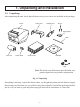
1. Unpacking and Installation 1-1. Unpacking After unpacking the unit, check that all the necessary accessories are included in the package. Printer Cable cover Holding plate Screws Roll stoppers Shaft Paper roll Switch blind Setup sheets CD-ROM Note Note: The ferrite core and fastener provided with your printer depend on your printer configuration. Fig. 1-1 Unpacking If anything is missing, contact the dealer where you bought the printer and ask them to supply the missing part.
1-2. Choosing a place for the printer Before actually unpacking the printer, you should take a few minutes to think about where you plan to use it. Remember the following points when doing this. Choose a firm, level surface where the printer will not be exposed to vibration. The power outlet you plan to connect to for power should be nearby and unobstructed. Make sure that the printer is close enough to your host computer for you to connect the two.
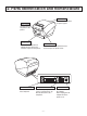
2. Parts Identification and Nomenclature Printer cover Open this cover to load or replace paper. Power switch Used to turn on/ off power to the printer. Control panel Features LED indicators to indicate printer status and switches to operate the printer. Interface connector For connection to a host computer. Cover open lever Push this lever in the direction of the arrow to open the printer cover. Peripheral drive connector Connects to peripheral units such as cash drawers, etc.
3. Setup 3-1. Connecting the Cable to the PC 3-1-1. Parallel Interface Cable Connect the parallel interface cable to a parallel port of your PC. 3-1-2. RS-232C Interface Cable Connect the RS-232C interface cable to a RS-232C port of your PC. 3-1-3. USB Interface Cable Connect the USB interface cable to a USB port of your PC. 3-1-4. Ethernet Interface cable Connect the ethernet interface cable to a ethernet port of your PC.
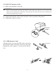
3-2. Connecting the Cable to the Printer Note that the interface cable is not provided. Please use a cable that meets specifications. CAUTION Before connecting/disconnecting the interface cable, make sure that power to the printer and all the devices connected to the printer is turned off. Also make sure the power cable plug is disconnected from the AC outlet. 3-2-1. Parallel Interface Cable (1) Make sure the printer is turn off. (2) Affix the ferrite core onto the cable as shown in the illustration.
3-2-2. RS-232C Interface Cable (1) Make sure the printer is turn off. CAUTION Before connecting/disconnecting the interface cable, make sure that power to the printer and all the devices connected to the printer is turned off. Also make sure the power cable plug is disconnected from the AC outlet. (2) Connect the interface cable to the connector on the rear panel of the printer. (3) Tighten the connector screws. RS-232C interface cable 3-2-3.
3-2-4. Connecting Ethernet Cable When using an Ethernet cable that is 10 m or less, shielded cable is recommended. (1) Make sure the printer is turned off. (2) Affix the ferrite core onto the ethernet cable as shown in the illustration below. (3) Pass the fastener through the ferrite core. (4) Loop the fastener around the cable and lock it. Use scissors to cut off any excess.
3-3. Installing the Printer Software Here is the procedure for installing the printer driver and utility software, which are stored on the supplied CD-ROM. The procedure applies to the Windows operating systems shown below. • Windows 2000 • Windows XP • Windows Vista (1) Turn ON the power to your PC to start Windows. (2) Insert the supplied CD-ROM (Drivers and Utilities) into the CD-ROM drive. (3) Follow the instructions that appear on the screen.
3-4. Connecting the Optional AC Adapter Note: Before connecting/disconnecting the AC adapter, make sure that power to the printer and all the devices connected to the printer is turned off. Also make sure the power cable plug is disconnected from the AC outlet. (1) Connect the AC adapter to the power cable. Note: Use only the standard AC adapter and power cable. (2) Connect AC adapter to the connector on the printer. (3) Insert the power cable plug into an AC outlet.
3-5. Turning Power On Make sure that the Power cord has been connected as described in 3-4. Turn ON the power switch located on the front of the printer. The POWER lamp on the control panel will light up. Power switch CAUTION We recommend that you unplug the printer from the power outlet whenever you do not plan to use it for long periods. Because of this, you should locate the printer so that the power outlet it is plugged into is nearby and easy to access.
3-6. Connecting to a Peripheral Unit You can connect a peripheral unit to the printer using a modular plug. See “Modular plug” on page 58 for details about the type of modular plug that is required. Note that this printer does not come with a modular plug or wire, so it is up to you to obtain one that suits your needs. CAUTION Make sure that the printer is turned off and unplugged from the AC outlet and that the computer is turned off before making connections.
3-7. Loading the Paper Roll Be sure to use paper roll that matches the printer’s specification. 1 Push the cover open lever and open the printer cover. 2 Set the paper roll in the direction as shown, and pull on the leading edge of the paper towards you. Cover open lever Paper roll Tension bar Note: Make sure not to pass the paper under the tension bar.
3-7-1. Removing the Tension Bar When using thermal paper roll, the tension bar unit may or may not be necessary, depending on the paper thickness, paper width, or the installation layout. If the tension bar unit is unnecessary, remove it in accordance with the procedure indicated below. The tension bar unit is unnecessary when using full-face thermal label paper roll or thermal label paper roll (tack label paper).
3-7-2. Changing the Adjustment Lever Position The adjustment lever position must be changed in accordance with the paper thickness. It is factory-set to position ①. When using paper thickness between 100 and 150 μm, change the adjustment lever position in accordance with the procedure below. As shown, use a flat head screwdriver to move the adjustment lever inward. Then, lower the adjustment lever to the position in which the protrusion on the adjustment lever engages with the hole in the frame.
Caution Symbol This symbol is placed near the thermal head to indicate that it may be hot. Never touch the thermal head immediately after the printer has been used. Let the thermal head cool for a few minutes before touching it. This symbol is placed near the thermal head to indicate that it is easily damaged. Observe the precautions for handling electrostatic sensitive devices. WARNING 1) Do not touch the cutter blade. • There is a cutter inside the paper outlet slot.
Notes on Using the Auto Cutter 1) To print after a cut, feed 1 mm (8-dot line) or more of paper. 2) If the cutter is not in its home position after an error, first eliminate the cause of the error; then, turn the power back ON. 3) If the printer is placed horizontally, the use of the partial cut is recommended. If you use the full cut, the cut pieces of paper may fall into the paper outlet passage, causing a paper jam as a result of cutting multiple pieces of paper.
4. Attaching the Accessories The following accessories do not necessarily have to be attached. Attach them if necessary. • Holding plate • Cable cover • Switch blind 4-1. Attaching the Holder Plate Shaft (1) Attach the shaft to the printer. Push in the left and right ends of the shaft. (2) Wipe the area into which the rubber feet will be affixed in order to remove any grime; then, affix the roll stoppers. The positions for affixing them will vary depending on the paper width. 82.5 or 79.
(4) Attach the holding plate to the printer. Then tighten the two screws that were supplied to secure it in place. (5) Position the printer over the screws, etc., on the wall and then slide it downward to set it in place. CAUTION The weight of the printer, including a roll of paper with the largest diameter, is approximately 2.4 kg. The screws installed in the wall must have both a shear and tensile strength capable of withstanding a load of 12 kgf (118 N) or more.
4-2. Attaching the Switch Blind Attach the switch blind as shown in the illustration. 4-3. Switch Blind Installation It is not necessary to install the switch blind. Only install it if it is necessary for you. By installing the switch blind, the following become possible. • Preventing the power switch from being operated by mistake. • Ensuring that other people can not easily operate the power switch. Install the switch blind as shown in the diagram below.
5. Consumable Parts and AC Adapter When consumable parts have run out, use those specified in the table below. Make sure that the AC adapter specified in the table is used. Use of consumable parts or AC adapter which are not specified in the table may result in damage to the printer, fire or electric shock. 5-1. Thermal Paper Roll (1) Paper roll specification Width: 79.5±0.5 mm or 82.5±0.5 mm or 57.5±0.5 mm Outer roll diameter: ø100 mm or less mm or 83+0.5 mm or 58+0.
Manufacture Product name Quality characteristics/Use Oji Paper Co., Ltd. PD150R PD160R PD750R PD700R TF50KS-E2C P320RB P320BB 130LHB normal type paper high image stability paper 2 color paper: Red & Black 2 color paper: Blue & Black normal type paper 2 color paper: Red & Black 2 color paper: Blue & Black high image stability paper, card ticket Nippon Paper Industries Kanzaki Speciality Papers Inc.
5-2. Full-Face Thermal Label Paper Roll (1) Label paper specification Backing paper width: 79.5±0.5 mm or 82.5±0.5 mm Outer roll diameter: ø100 mm or less mm or 83+0.5 mm Take up paper roll width: 80+0.5 -1 -1 Thickness: Max. 150 μm Core outer/inner diameter: core inner diameter ø25.4±1 mm/core outer diameter ø32±1 mm Printed surface: Outer edge of roll Tail end handling: Do not use paste or glue to secure the paper roll or its core. Do not fold the tail end of the paper.
(3) Effective Print Width Paper Width (mm) 79.5 ± 0.5 82.5 ± 0.5 Right / Left Margin (mm) 4 Left -2 to 1, Right 1.5 to 3 Left Margin Effective Print Width (mm) 72 80 Effective Print Width Number of Print Columns (12 ×24 Font) 48 53 Right Margin Paper Width 5-3. Thermal Label Paper Roll (Tack Label Paper) (1) Label paper specification Backing paper width: 79.5±0.5 mm or 82.5±0.5 mm Outer roll diameter: ø100 mm or less mm or 83+0.5 mm Take up paper roll width: 80+0.5 -1 -1 Thickness: Max.
(2) Recommended label paper Manufacturer Product name Lintec LD2114 Lintec LD5530 Ricoh 130LHB Quality features/ applications For distribution or information control For measurement For distribution or information control Base material 65 Thickness (μm) 41 Total thickness 115 85 65 150 85 – – Separator Adhesion type High adhesion High adhesion High adhesion Note: 1) Depending on the type and thickness of the paper, it may be necessary to change the settings for printing darkness.
• Detailed Diagrams of Recommended Tack Label Specifications Tack label ø32 ± 1 ø100 MAX ø25.4 ± 1 Paper tube Base material (label paper) 30 – 295 (Label length) 5 PCS: 0.90 minimum 5 ± 1.0 1.75 ± 0.5 Black mark (back of diagram) 15 MIN 1 +1.0 -0.8 76 ± 0.5 (Label width) Printing direction 79.5 ± 0.5 (Backing paper width) Release paper (backing paper) (1.75) 80 +0.5 -1.0 (Rolled dimension) 35 – 300 (Black mark pitch) [Details of recommended tack label specifications (for 79.
• Detailed Diagram of Effective Printing Range 70 (effective printing width: 46 characters with font A) 3 (Left margin) Dot numbers 39 – 598 3 (Right margin) 30 – 295 (Label length) 35 – 300 (Black mark pitch) 22.5 – 287.5 (Effective printing length) 3 (Bottom margin) 4.5 (Top margin) * Minimum settable top margin when paper is fed using back-feed. Effective printing range 1.75 ± 0.5 76 ± 0.5 (Label width) 79.5 ± 0.5 (Backing paper width) (1.75) 79.
5-4. AC adapter (option) 5 Approx. 14 Approx. 13 2.5 2.5 • Cut Position / Printing Line / Black Mark Sensor’s Positional Relationship Cut position Printing line Black mark sensor AC adapter which are not specified may result in damage to the printer, fire or electric shock. Model name: PS60A-24A Input: 100 to 240 V AC, 50/60 Hz Output: DC24±5%, 2.0 A (5.0 A Load 10 sec. Max.
6. Control Panel and Other Functions 6-1. Control Panel ① POWER lamp (Green LED) When the printer is online, power lamp is ON and ERROR lamp is OFF. ② ERROR lamp (Red/Orange LED) Indicates various errors in combination with POWER lamp. ③ FEED button Press the FEED button to feed paper roll. ③ FEED button ② ERROR lamp (Red/Orange LED) ① POWER lamp (Green LED) 6-2. Errors 1) Recoverable errors Error Description Head high temperature detection Cover open error POWER Lamp Flashes at 0.
2) Non-recoverable errors Error Description Flash access error POWER Lamp OFF EEPROM error OFF SRAM error OFF Head thermistor error OFF Power voltage error OFF ERROR Lamp Flashes Orange lamp at 0.5-second intervals Flashes Red lamp at 0.75second intervals Flashes Orange lamp at 1-second intervals Flashes Red lamp at 1.5-second intervals Flashes Orange lamp at 2-second intervals Recovery Conditions This is not a recoverable error. This is not a recoverable error. This is not a recoverable error.
6-3. Self-Printing 6-3-1. Test Printing Place the thermal paper roll on the printer. Turn the power ON while holding the FEED button depressed. The printer will run a test print according to the Ver. No., DIP switch settings, and memory switch settings, etc. 6-3-2. Hexadecimal Dump Mode Place the thermal paper roll on the printer. Open the printer cover, then turn the power on while holding the FEED button.
7. Adjusting the Near-end Sensor Use the following procedure to adjust the near-end sensor so it is compatible with the size of paper roll you are using. However, for vertical or wall-mount use, keep the adjuster fixed to level 3, without changing its position. ① Open the printer cover. ② Determine the diameter of the paper roll you are using and find the required setting in the table below.
Adjustment value according to the paper you are using Paper thick-ness (µm) 65 75 Paper thick-ness (µm) 65 75 85 95 105 130 150 When using the paper roll with a core whose inside diameter (A):ø12, outside diameter (B):ø18 Detected diameter (C) Remained paper length (Approx. mm) (Approx. m) Level 1 Level 2 Level 3 Level 1 Level 2 Level 3 ø23 ø27 ø31 2.5 4.9 7.7 2.1 4.2 6.7 When using the paper roll with a core whose inside diameter (A): ø25.
8. Preventing and Clearing Paper Jams 8-1. Preventing Paper Jams The paper should not be touched during ejection and before it is cut. Pressing or pulling the paper during ejection may cause a paper jam, paper cutting failure or line feed failure. 8-2. Removing Paper Jam If a paper jam occurs, clear it as described below. (1) Set the power switch to off to turn off power to the printer. (2) Push the lever toward you to open the printer cover. (3) Remove the jammed paper.
9. Periodical Cleaning Printed characters may become partially unclear due to accumulated paper dust and dirt. To prevent such a problem, paper dust collected in the paper holder and paper transport section and on the surface of the thermal head must be removed periodically. Such cleaning is recommended to be carried out once six month or one million lines. If the printer uses label paper, clean it on a monthly basis or after printing approximately 200,000 lines. 9-1.
10. Specifications 10-1. General Specifications Printing method Direct line thermal printing Print speed Max. 2000 dots/sec. (250 mm/sec.) Dot density 203 dpi: 8 dots/mm (0.125 mm/dot) Printing width Max. 80 mm Number of print columns 53 (12 × 24 dots) Paper roll Refer to chapter 4 for details on the recommended paper roll. Paper width: 79.5 ± 0.5 or 82.5 ± 0.5 or 57.5 ± 0.5 mm Roll diameter: ø100 mm or less (7) Overall dimension 147 (W) × 213 (D) × 148 (H) mm Approx. 1.
10-2. Auto Cutter Specifications (1) Cutting frequency (2) Thickness of paper Max. 20 cuts per minute 0.065 ~ 0.15 mm 10-3. Interface RS-232C serial interface/Two-way parallel interface (IEEE1284)/USB interface/Ethernet interface/Wireless LAN Interface 10-4. Electrical Characteristics (1) Input Voltage DC 24 V±10% (2) Current Consumption (DC 24 V at room temperature) Approx. 0.15 A Standby: ASCII printing: Approx. average 1.8 A (Approx. 17.5% printing rate) 100% print duty: Approx. peak 11.
10-5.
10-6. Reliability Specifications (1) • • • (2) • • • • MCBF: 60 million lines Recommended thermal paper (60 μm to 75 μm) Average printing rate: 12.5% Printing density: standard setting Note: The Mean Cycles Before Failure (MCBF) with the recommended thermal paper thickness between 75 μm and 150 μm is 25 million lines. Auto cutter (life) Paper width 82.5 mm, 79.5 mm *Including backing paper Paper thickness between 65 μm and 100 μm: 2 million partial cuts, 1.
10-7. Black mark specifications Reverse side of the paper Dimension A = 30 to 300 mm 5 ± 1 mm +1 1 -0.8 mm 15 mm or more 2.5 mm Printing direction Printing area Upper margin 14 mm or more Bottom margin Cut position The reverse side of the paper is the printing surface. (3 mm + dimension A × 3%) or more 1) The cut position shown above is when the print starting position correct value for Appendix F: memory switch 9 is the default setting. 2) The black mark’s PCS value must be 0.
11. Dip Switch Setting Two DIP switches are provided at the bottom of the printer, and can be set as given in the table below. Be sure to set the power switch to off before changing the settings. It is recommended to use a pointed item like a pen or flat-blade driver screw to change the settings. The settings will become effective when the power switch is set to on again. The following is the procedure for changing the settings on DIP switches. 1. Make sure the printer is turned off. 2.
11-1. Parallel Interface Model ON ON OFF No. 1 2 3 4 5 6 7 8 9 10 OFF No. 1 2 3 4 DIP-SW 1 Switch 1-1 ON OFF DIP-SW 2 DIP-SW 1 Command emulation Star Mode ESC/POS Mode The factory settings of DIP switch are all on. The functions of switches 1-2 through 1-10 will change according to the command emulation that has been set using switch 1-1.
Switch 2-1 2-2 2-3 2-4 Function DIP-SW 2 Always ON ON OFF Should be set to on The factory settings of DIP switch are all on.
11-2. RS-232C Interface Model ON ON OFF No. 1 2 3 4 5 6 7 8 9 10 OFF No. 1 2 3 4 DIP-SW 1 Switch 1-1 ON OFF DIP-SW 2 DIP-SW 1 Command emulation Star Mode ESC/POS Mode The factory settings of DIP switch are all on. The functions of switches 1-2 through 1-10 will change according to the command emulation that has been set using switche 1-1.
Switch 2-1 2-2 2-3 2-4 Function DIP-SW 2 Always ON ON OFF Should be set to on The factory settings of DIP switch are all on.
The following is the procedure for changing the settings on DIP switch No. 3. 1. Turn off the printer and all components connected to it. 2. Remove the 2 screws. 3. Remove the serial interface board unit. 4. Change the setting of the DIP switches. 5. Replace the serial interface board unit. Then secure it with the screws. 6. Turn on the printer and all components connected to it. ON OFF No. 1 2 3 4 5 6 7 8 DIP-SW 3 DIP switch 3 The factory settings of DIP switch are all on, except for switches 7 and 8.
11-3. USB Interface Model ON ON OFF No. 1 2 3 4 5 6 7 8 9 10 OFF No.
11-4. Ethernet Interface Model ON ON OFF No. 1 2 3 4 5 6 7 8 9 10 OFF No.
■ Initializing Settings Set the push switch as described below to initialize the setting information. Push the switch for one to five seconds while running under normal operating mode. The green and red LEDs will flash with a regular pattern. After that, push the switch once again in that state to turn OFF both of the red and green LEDs. This will return the settings of the interface board to their default, or ex-factory, settings.
Switch 2-1~2-4 Function Always ON DIP-SW 2 ON OFF Should be set to on The factory settings of DIP switch are all on. OFF ON No. 1 2 DIP-SW 3 LED DIP Switch 3 DIP Switch 3-1 3-2 ON Initialize of setting information Fixed at OFF OFF — Change DIP Switch 3-2 to ON initialize the setting information when the power is turned on. The factory settings of DIP switch are all off. LED Display Green : Lights when pockets are received.
Note: • This product contains a built-in wireless device and can only be used in the following countries. USA, UK, France, Ireland, Belgium, Germany, Austria, Switzerland, Italy, Denmark, Norway, Sweden, Portugal, Spain, Estonia, Finland, Greece, Luxemburg, Netherlands, Canada, Slovakia, Slovenia, Czech, Hungary, Poland, Latvia, and Lithuania. • This product contains Transmitter Module which conforms to the R&TTE Directive. • This product contains Transmitter Module FCC ID: M4B6180210.
Connecting the peripheral drive cable Connect the peripheral drive cable to the connector on the printer. Then, connect the other end of the cable to the peripheral drive circuit.
12. Parallel Interface The two-way parallel interface is compatible with the IEEE1284 compatibility mode and nibble mode. Refer to the separate Specifications Manual for details. Table of Connection Signals for Each Mode Pin No.
13. RS-232C Serial Interface 13-1. Interface Specifications ① Data transmission method: ② Baud rate: ③ Word length ④ Signal polarity Asynchronous serial interface Selectable from 4800, 9600, 19200, 38400 bps (Refer to “11. DIP Switch Setting”.) Start bit: 1 bit Data bit: 7 or 8 bits (selectable.) Parity bit: Odd, even or none (selectable.
13-2. RS-232C Connector Pin No. 1 2 3 4 5 6 Signal name F-GND TXD RXD RTS N/C DSR Direction — OUT IN OUT 7 8~19 20 S-GND N/C DTR — IN OUT Function Frame ground Transmission data Receive data Same as DTR signal. Not used STAR Mode Status of this signal is not checked. ESC/POS Mode In DTR/DSR communication mode, indicates whether data receive from host is enabled or disabled.
Pin No. Signal name Direction Function 1) DTR/DSR Communication Mode This signal indicates whether the printer is busy. SPACE indicates that the printer is ready to receive data, and MARK indicates that the printer is busy. The busy condition can be changed by using DIP SW 1-6 as follows: DIP SW 1-6 Printer status OFF ON BUSY BUSY BUSY BUSY — BUSY 5. During macro executing standby status. — BUSY 7. When the receive buffer becomesfull. — BUSY BUSY BUSY 1.
13-3. Cable Connections The followings are a recommended interface cable connections. Printer side Host side 25 pin 9 pin FG 1 1 FG TXD 2 2 3 TXD RXD 3 3 2 RXD RTS 4 4 7 RTS CTS 5 5 8 CTS DSR 6 6 6 DSR SG 7 7 5 SG DTR 20 8 1 DCD INIT 25 20 4 DTR Note: Use shielded wire less than 3 m in length. 13-4.
14. USB, Ethernet and Wireless LAN Interface 14-1. USB Interface Specifications 1. 2. 3. 4. 5. General Specification: Communication Speed: Communication Method: Power Specifications: Connector: Conforms to USB 2.0 Specifications USB Full Speed Mode (12 Mbps) USB Bulk Transmission Mode USB Self-power Function USB Up-Stream Port Connector (USB Type-B) 14-2. Ethernet Interface Specifications 1. General Specification: Conforms to IEEE802.3 2. Communication Media: 10 Base-T/100 Base-TX 3.
15. Peripheral Unit Drive Circuit Peripheral unit drive circuit connector only connects to peripheral units such as cash drawers, etc. Do not connect it to a telephone. Use cables which meet the following specifications.
Reference 2SD 1866 Circuit Configuration Drive Output: 24 V, Max. 1.0 A Transistor 2SD 1866 or equivalent TR1, TR2: R1=10 kW R2=33 kW Note: 1. Pin 1 must be shield drain wire connected to peripheral device frame ground. 2. It is not possible to drive two drives simultaneously. 3. The peripheral drive duty must satisfy the following: ON time / (ON time + OFF time) 0.2 4. Minimum resistance for coils L1 and L2 is 24 Ω. 5.
16. Memory Switch Settings Each memory switch is stored in EEPROM. For details on the functions and settings of memory switches, see the separate Specification Manual. The table below shows the factory settings for the memory switches. Memory Switch 0 1 2 3 4 5 6 7 8 9 Hexadecimal Code 0000 0000 0000 0000 0000 0000 0000 0000 0000 0000 WARNING Changing the memory switch settings can cause the printer to fail to operate correctly.
Oki Data Americas, Inc., 2000 Bishops Gate Blvd., Mt.Laurel, NJ 08054-4620 Tel: 1-800-Oki-Data (1-800-654-3282) Fax: (856) 222-5320 www.okiprintingsolutions.com Oki Data de Mexico, S.A. de C.V., Mariano Escobedo NO. 748-8 Piso, Col. Anzures, e.p. 11590, Mexico, DF Tel: 52-555-263-8780 Fax:52-555-250-3501 www.okiprintingsolutions.