
Printer Developer's Guide
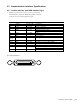
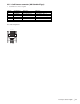
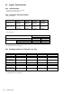
Table Of Contents
- Contents
- 1. Setting Up the Printer
- 1.1. Select a Location
- 1.2 Where to install your printer
- 1.3 Unpacking
- 1.4 Installing the Printer
- 1.5 Installing the Paper
- 2. Using the Printer
- 3. Maintenance
- 4. Troubleshooting and Repair
- 5. Specifications
- 5.1 Introduction
- 5.2 General Specifications
- 5.3 Communication Interface Specifications
- 5.4 Physical Characteristics
- 5.5 Logical Characteristics
- 5.6 Printer Performance
- 5.7 Media Specifications
- 5.8 Paper Feed Specifications
- 5.9 MICR Specifications (Only with MICR type)
- 5.10 Auto Cutter Specifications
- 5.11 Ribbon Specifications
- 5.12 Reliability
- 6. Command Description
- 7. Using the Unitool Printer Driver
- 1. Setting Up the Printer
|
Developer’s Guide: English 65
5.3 Communication Interface Specifications
5.3.1 Parallel Interface (OKI/OEM Standard Type)
1 Interface Spec (Between centronics connector and host PC)
Parallel interface signal part (IEEE-1284 parallel equivalent)
Centronics Connector Pin Assignment signal
A25012.doc
Pin No. Signal Name Direction Function
1 nStrobe From host PC Data Strobe
2-9 DATA bit 1~8 From host PC Data from host PC
10 nAck To host PC Receive completion
11 Busy To host PC Data receiving impossible
OEM Standard Type: Error12 PError To host PC
OKI Standard Type: Paper End
13 Select To host PC Online
14 nAutoFd From host PC 1284 mode move request
15 NC - Not connected
16,19-
30, 33
GND - Signal ground
17 FG - Frame ground
18,35 +5V To host PC +5VDC power supply (Max 400mA)
31 nInit From host PC Initialization
32 nFault To host PC Error
OEM Standard Type: Not used34 DK_STATUS To host PC
OKI Standard Type: Cash Drawer status signal
36 nSelectln From host PC 1284 mode move request
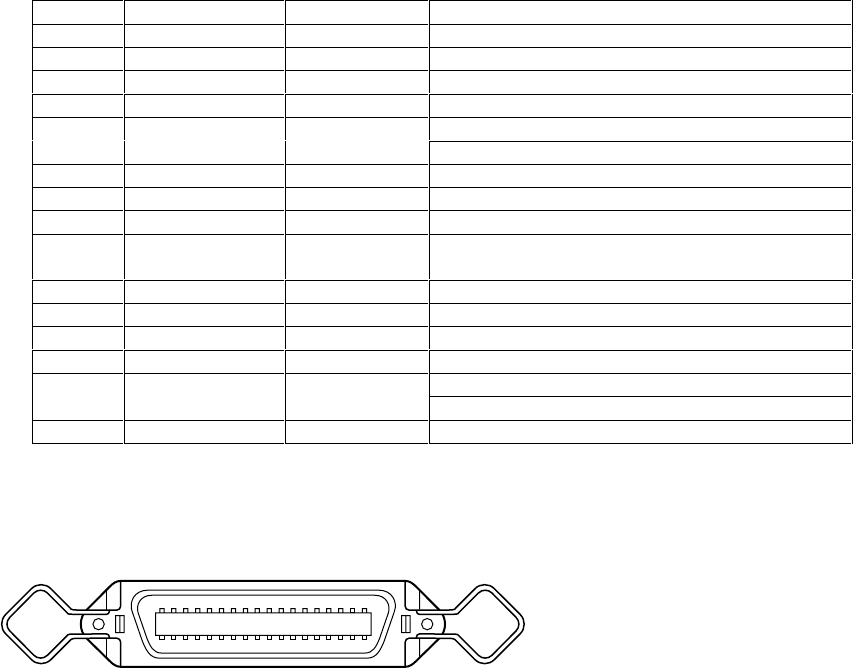
Note: Pin arrangement
OP425_05.eps
118
1936