OkiPos 441 User’s Guide 59307701
Federal Communications Commission Radio Frequency Interference Statement This equipment has been tested and found to comply with the limits for a Class A digital device, pursuant to Part 15 of the FCC Rules. These limits are designed to provide reasonable protection against harmful interference when the equipment is operated in a commercial environment.
TABLE OF CONTENTS 1. Outline........................................................................................................................................................1 2. Unpacking and Installation......................................................................................................................2 2-1. Unpacking.....................................................................................................................................2 2-2.
13. USB, Ethernet and Wireless LAN Interface.......................................................................................50 13-1. USB Interface Specifications......................................................................................................50 13-2. Ethernet Interface Specifications.................................................................................................50 13-3. Wireless LAN Interface Specifications.........................................................
1. Outline OKIPOS441 Series Serial Impact Dot Matrix Printer is designed for use with electronic instruments such as POS, banking equipment, computer peripheral equipment, etc.
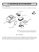
2. Unpacking and Installation 2-1. Unpacking After unpacking the unit, check that all the necessary accessories are included in the package. Ribbon cartridge Note Setup sheets CD-ROM Printer Switch blind Roll paper guide Power cord Note: The ferrite core and fastener provided with your printer depend on your printer configuration. Fig. 1-1 Unpacking If anything is missing, contact the dealer where you bought the printer and ask them to supply the missing part.
2-2. Choosing a place for the printer Before actually unpacking the printer, you should take a few minutes to think about where you plan to use it. Remember the following points when doing this. 3 Choose a firm, level surface where the printer will not be exposed to vibration. 3 The power outlet you plan to connect to for power should be nearby and unobstructed. 3 Make sure that the printer is close enough to your host computer for you to connect the two.
2-3. Handling Care 1. 2. 3. 4. 5. 6. Be careful not to drop paper clips, pins or other foreign matter into the unit as these cause the printer to malfunction. Do not attempt to print when either paper or ribbon cartridge is not located in the printer, otherwise the print head can be damaged. Do not open the cover while printing. Do not touch the print head immediately after printing as it gets very hot. Use only roll paper that is not glued to the core.
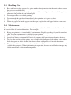
3. Parts Identification and Nomenclature Printer cover Protects the printer from dust and reduces noise. Do not open the cover while printing. Control panel Power switch Features one control switch and two indicators to indicate printer status. Turns printer power on and off. Power connector For connection of the power cord. Peripheral unit drive circuit connector Connects to peripheral units such as cash drawers, etc. Do not connect this to a telephone.
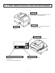
4. Setup 4-1. Connecting the Cable to the PC 4-1-1. Parallel Interface Cable Connect the parallel interface cable to a parallel port of your PC. 4-1-2. RC-232 Interface Cable Connect the RC-232 interface cable to a RS-232 port of your PC. 4-1-3. USB Interface Cable Connect the USB interface cable to a USB port of your PC. 4-1-4. Ethernet Interface cable Connect the ethernet interface cable to a ethernet port of your PC.
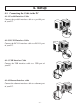
4-2. Connecting the Cable to the Printer Note that the interface cable is not provided. Please use a cable that meets specifications. CAUTION Before connecting/disconnecting the interface cable, make sure that power to the printer and all the devices connected to the printer is turned off. Also make sure the power cable plug is disconnected from the AC outlet. 4-2-1. Parallel Interface Cable (1) Make sure the printer is turn off. (2) Affix the ferrite core onto the cable as shown in the illustration.
4-2-2. RS-232 Interface Cable (1) Make sure the printer is turn off. CAUTION Before connecting/disconnecting the interface cable, make sure that power to the printer and all the devices connected to the printer is turned off. Also make sure the power cable plug is disconnected from the AC outlet. (2) Connect the interface cable to the connector on the rear panel of the printer. (3) Tighten the connector screws. 4-2-3.
4-2-4. Connecting Ethernet Cable (1) Make sure the printer is turned off. (2) Affix the ferrite core onto the ethernet cable as shown in the illustration below. (3) Pass the fastener through the ferrite core. (4) Loop the fastener around the cable and lock it. Use scissors to cut off any excess. 1 cm (maximum) Ethernet cable Ferrite core Fastener (5) Connect the interface cable to the connector on the rear panel of the printer.
4-3. Installing the Printer Software Here is the procedure for installing the printer driver and utility software, which are stored on the supplied CD-ROM. The procedure applies to the Windows operating systems shown below. • Windows 2000 • Windows XP • Windows Vista (1) Turn ON the power to your PC to start Windows. (2) Insert the supplied CD-ROM (Drivers and Utilities) into the CD-ROM drive. (3) Follow the instructions that appear on the screen.
4-4. Connecting to a Peripheral Unit You can connect a peripheral unit to the printer using a modular plug. See “Modular plug” on page 33 for details about the type of modular plug that is required. Note that this printer does not come with a modular plug or wire, so it is up to you to obtain one that suits your needs. Important! Make sure that the printer is turned off and unplugged from the AC outlet and that the computer is turned off before making connections.
4-5. Connecting the Power Cord Note: Before connecting/disconnecting the power cord, make sure that power to the printer and all the devices connected to the printer is turned off. Also make sure the power cable plug is disconnected from the AC outlet. (1) Check the label on the back or bottom of the printer to make sure its voltage matches that of the AC outlet. Also make sure the plug on the power cord matches the AC outlet.
4-6. Turning Power On Make sure that the Power cord has been connected as described in 4-5. Turn ON the power switch located on the front of the printer. The POWER lamp on the control panel will light up. Power switch CAUTION We recommend that you unplug the printer from the power outlet whenever you do not plan to use it for long periods. Because of this, you should locate the printer so that the power outlet it is plugged into is nearby and easy to access.
4-7. Installing the Cable Install the cable as shown in the diagram below. 4-8. Switch Blind Installation It is not necessary to install the switch blind. Only install it if it is necessary for you. By installing the switch blind, the following become possible. • Preventing the power switch from being operated by mistake. • Ensuring that other people can not easily operate the power switch. Install the switch blind as shown in the diagram below.
5. Loading the Ribbon Cartridge and Paper 5-1. Loading the Ribbon Cartridge 1 Turn off power to the printer. 2 Open the front cover by holding the finger grips on both ends of the cover and lifting it up. Important! 1. Do not touch the print head immediately after printing as it can be extremely hot. 2. Do not touch the cutter blade. · There is a cutter inside the paper outlet slot.
5-2. Loading the paper 1 Open the printer cover by sliding the latch toward you. Important! 1. Do not touch the print head immediately after printing as it can be extremely hot. 2. Do not touch the cutter blade. · There is a cutter inside the paper outlet slot. Not only should you not put your hand in the paper outlet slot while printing is in progress, never put your hand into the outlet even when printing is not in progress.
4 Tear Bar Model: Tear off the paper as shown. Auto Cutter Model: If the printer cover is closed after turning on the power, the cutter operates automatically and the front end of the paper is cut. Note: When the paper end mark appears on the paper, replace the roll paper before it runs out.
5-3. Installing the Roll Paper Guide When using paper roll with 57.5 mm or 69.5 mm width, install the attached roll paper guide in the groove in the printer. The setting for memory switch 2-A and 2-B must be changed to change the print width. For instructions on setting the memory switch, please refer to the separate Specification Manual. 69.5 mm width Roll paper guide Roll paper guide 57.
Caution Symbol This symbol is placed near the print head to indicate that it may be hot. Never touch the print head immediately after the printer has been used. Let the print head cool for a few minutes before touching it. This symbol is placed near the cutter (auto cutter or manual cutter tear bar). Never touch the cutter blade, as you could injure your fingers. This symbol label or stamp is placed near the screws securing the case, which should not be opened by individuals other than service personnel.
CAUTION 3 We recommend that you unplug the printer from the power outlet whenever you do not plan to use it for long periods. Because of this, you should locate the printer so that the power outlet it is plugged into is nearby and easy to access. 3 If the voltage shown on the label on the of your printer does not match the voltage for your area, contact your dealer immediately.
6. Control Panel and Other Functions 6-1. Control Panel 1POWER lamp (Green LED) Lights when the power is ON. 2FEED button Press the FEED button to feed roll paper. 3ERROR lamp (Red LED) Indicates various errors in combination with POWER lamp. 2 FEED button 3 ERROR lamp (Red LED) 1 POWER lamp (Green LED) 6-2.
6-3. Errors 1) Recoverable error Error Description Paper end error POWER lamp ERROR lamp Buzzer On Flashes (On: 1 sec./ On On 4 short beeps (0.13 sec.) repeated twice Beep Flashes (On: 0.5 sec./Off: 0.5 sec.) On On Beep *3 Flashes (On: 2 sec./Off: 2 sec.) Off None *4 None *5 Off None *6 Flashes (On: 0.125 sec./Off: 0.125 sec.) Flashes (On: 0.25 sec./Off: 0.25 sec.) Flashes (On: 0.5 sec./Off: 0.5 sec.) 3 short beeps (0.13 sec. + 0.13 sec. + 0.5 sec.) 2 short beeps (0.13 sec. + 0.5 sec.
*7 Automatically the printer is recovered if the cutter returns to the home position after turning the power OFF and ON. Restoration is also possible with the n command when in the ESC/POS mode. Note 1) If the cutter doesn’t return to the home position, or doesn’t perform the initial movement, it cannot be recovered. 2) If the paper is jammed, turn the power OFF, clear the jammed paper, then turn the power ON.
6-4. Adjustment Mode There are the following seven adjustment modes. The device will enter the adjustment mode if your turn it on while pressing the FEED switch. (1) The Self Printing Mode is entered by releasing the FEED switch after the buzzer sounds once. (Refer to Section 6-4-1.) (Holding down for 2 more seconds) (2) Adjusting the Dot Alignment Mode is entered by releasing the FEED switch after the buzzer sounds twice. (Refer to Section 6-4-2.
6-4-1. Self Printing Mode Self-printing will be performed to print the Ver. No. and printer settings. ASCII-printing will be repeated when the FEED switch is held continuously at the end of ASCII-printing. The self-printing mode will end automatically when the FEED button is released at the end of ASCII‑printing.
6-4-2. Adjusting the Dot Alignment Mode You may never have to use the procedure described in this section, but after you have been using your printer for some time you may find that the dots of some graphics do not align correctly. For example, what should look like: may come out looking like one of the following: or like this This is caused when mechanical parts of the printer get out of alignment. This happens only rarely and you may never experience it at all throughout the life of the printer.
(3) To adjust, use the FEED switch to select the adjustment pattern from the printout with the smallest gap between the first printing pass and the return printing pass. Press the FEED switch once to specify the first adjustment pattern, twice to specify the second adjustment pattern, and so on up to seven times to specify the seventh adjustment pattern. At the number that you want to specify, press and hold (2 seconds) the FEED switch until the long buzzer sounds. This will specify the setting value.
6-4-3. Hexadecimal Dump Mode Each of the signals sent from the computer to the printer will be printed out in hexadecimal code. This function allows you to check if a control code sent to the printer by the program being used is correct or not. The last line is not printed if its data is less than one full line. However, if the FEED switch is pressed, the last line will be printed. To turn off the mode, it is necessary to turn off the printer completely.
6-4-4. Black Mark Sensor Alignment Mode 1. 2. Turn the printer off and unplug the power cord. Place the printer upright as shown below to remove the screws and remove the dip switch cover from the bottom of the printer. Be sure to place the printer upright because you will not be able to properly adjust the printer if it is placed on its side. Power OFF 1 8 VR2 VR1 3. 4. 5. 6. 7. Since it is adjusted by rotating the volume VR2, check the position of the volume.
7. Preventing and Clearing Paper Jams 7-1. Preventing Paper Jams The paper should not be touched during ejection and before it is cut. Pressing or pulling the paper during ejection may cause a paper jam, paper cutting failure or line feed failure. 7-2. Removing Paper Jam If a paper jam occurs, clear it as described below. (1) Set the power switch to off to turn off power to the printer. (2) Push the cover open lever, and open the printer cover.
7-3. Releasing a Locked Cutter (Auto Cutter Mode only) If the auto cutter locks up or fails to cut the paper, follow the steps below. WARNING Since working on the cutter may be dangerous, be sure to turn off the printer first. (1) Set the power switch to OFF to turn off the printer. (2) Ordinarily, a locked cutter will recover automatically by closing all the covers and turning the power back ON. Recovery means that the locked cutter has been released, so steps (3) and thereafter are unnecessary.
(6) After you have opened the printer cover, remove the four screws to remove the printer cover and reveal the cutter. Screws (7) If the cutter is locked, insert a Phillips screwdriver into the Phillips screw hole on the side of the cutter, and turn it in the direction of the arrow shown below, in order to return the cutter to its normal position. (8) Reinstall the printer cover by tightening its screws. (9) Reinstall the tear bar by tightening its screws.
8. Peripheral Unit Drive Circuit Peripheral unit drive circuit connector only connects to peripheral units such as cash drawers, etc. Do not connect it to a telephone. Use cables which meet the following specifications. Peripheral Drive Connector Function Frame ground Drive signal 1 Drive power Drive power Drive signal 2 Sense signal I/O direction — OUT OUT OUT OUT IN Modular plug: MOLEX 900750007, AMP641337, or FCI B-66-4 Shield Wire lead 6 Signal name FG DRD1 +24V +24V DRD2 DRSNS 1 Pin No.
Notes: 1. Peripheral units 1 and 2 cannot be driven simultaneously. To drive them continuously, set the duty cycle ratio to 20% or less (excluding an externally connected buzzer). Refer to the separate Specifications Manual for details. 2. The following external buzzer is available as an option. External buzzer model: RMB-24 Voltage rating: 24V Average consumption current: Max. 21 mA (at 24V) Sound pressure: Min. 75 dB at 1 m Lead wires: red (+) black (-) 3.
9. General Specifications 9-1. General Specifications Printing method: Serial impact dot matrix Print direction: Bi-directional Number of head pins: 9 wires Number of print columns: 42 columns Character set: ASCII 95 characters Extended graphics: 128 × 40 pages (Star mode) 128 × 9 pages (ESC/POS) International characters: 46 (Star mode) 37 (ESC/POS) Font configuration (ANK) 7 (Half dots) × 9 or 5 × 9 Printing width: 63 mm (210 dots)/57 mm (190 dots)/45 mm (150 dots) Print speed: Max. 4.
Ribbon material: Ribbon life: Nylon 66 (#40 denier) 441Ribbon Black/Red: Black 1,500,000 characters/Red 750,000 characters 441Ribbon Black: Black 3,000,000 characters Overall dimensions: 160 (W) × 245 (D) × 152 (H) mm 164 152 245 160 Weight: Interface Approx. 3.0 kg (Tear bar model) Approx. 3.2 kg (Auto cutter model) Parallel interface or RS-232C interface or USB Interface or Ethernet Interface or Wireless LAN Interface Peripheral unit drive circuit: 2 circuits (24V, max.
9-2. Power Supply Specifications Power Supply: Input: 100 to 240V AC, 50/60Hz Consumption Current: Conditions: Excluding perpheral unit driving Operating: Approx. 36 W (at ASCII printing) Stand-by: Approx.
10. Dip Switch Setting A DIP switch is provided at the bottom of the printer, and can be set as given in the table below. Be sure to set the power switch to off before changing the settings. It is recommended to use a pointed item like a pen or flat-blade driver screw to change the settings. The settings will become effective when the power switch is set to on again. The following is the procedure for changing the settings on DIP switches. 1. Make sure the printer is turned off. 2.
n DIP switch SW No. 1-1 1-2 1-3 1-4 1-5 1-6 1-7 1-8 Function ON Always ON Auto Cutter *1 Always ON Command emulation USB mode *2 2 colors printing Reserved Print head model *3 OFF Should be set on Invalid Valid Should be set on Star ESC/POS Printer class Vendor class Valid Invalid 18 pin wire 9 pin wire *1 The factory settings for enabling/disabling the auto cutter are as follows.
10-1. RS-232C Interface Model The RS-232C interface model is equipped with DIP switches on the serial interface board unit to change the communication settings. Change the settings for DIP switch No. 2 according to the following procedures. 1. Turn off the printer and all components connected to it. 2. Remove the 2 screws. 3. Remove the serial interface board unit. 4. Change the setting of the DIP switches. 5. Replace the serial interface board unit. Then secure it with the screws. 6.
10-2. Parallel Interface Model The parallel interface model is equipped with the main DIP switch only. 10-3. USB Interface Model The USB interface model is equipped with the main DIP switch only. 10-4. Ethernet Interface Model n Initializing Settings Set the push switch as described below to initialize the setting information. Push the switch for one to five seconds while running under normal operating mode. The green and red LEDs will flash with a regular pattern.
10-5. Wireless LAN Interface Model DIP-SW 2 Switch 2-1 2-2 ON OFF Fixed at OFF Initialize of setting information — Change DIP Switch 2-2 to ON to initialize the setting information when the power is turned on. The factory settings of DIP switch are all off. LED Display Green : Lights when pockets are received. ON OFF No. 1 2 DIP switch 2 LED DIP switch 2 Note: • This product contains a built-in wireless device and can only be used in the following countries.
* * * * This product contains Transmitter Module which conforms to the R&TTE Directive. This product contains Transmitter Module FCC ID: M4B6180210. This product contains Transmitter Module IC: 5844A-6180210. Strictly observe the export control laws of the country for export when exporting this product. Installing the Ferrite Core (Wireless LAN Model for EU Only) Install the ferrite core onto the peripheral drive cable to prevent radio interference.
Connecting the peripheral drive cable Connect the peripheral drive cable to the connector on the printer. Then, connect the other end of the cable to the peripheral drive circuit.
11. RS-232C Serial Interface 11-1. Interface Specifications 1 Data transmission method: 2 Baud rate: 3 Word length 4 Signal polarity Asynchronous serial interface Selectable from 4800, 9600, 19200, 38400 bps (Refer to “10. DIP Switch Setting”.) Start bit: 1 bit Data bit: 7 or 8 bits (selectable.) Parity bit: Odd, even or none (selectable.
11-2. Pins and Signal Names Pin No. 1 2 3 4 5 6 Signal Name FG TXD RXD RTS N.C. DSR 7 8 -19 20 SG N.C. DTR Direction — OUT IN OUT IN OUT Function Frame ground Transmission data Receive data Always space Not connected Dip switch 2-7 = OFF (1) STAR Mode Status of this signal is not checked. (2) ESC/POS Mode • In DTR/DSR communication mode Memory Switch 4-5 = “0”: signal line indicating whether host is enabled or disabled to receive data is checked.
Pin No. 20 Signal Name DTR 21 - 24 25 N.C. INIT Direction OUT Function X-On/X-Off Communication Mode Always space, except during following conditions: • Period between reset and communication enabled • During self printing and dot alignment adjustment Not connected Dip switch 2-8 = OFF Status of this signal is not checked. Dip switch 2-8 = ON This is an externally reset signal. A space above 1 ms pulse width engages reset. 13 1 25 14 11-3.
12. Parallel Interface The two-way parallel interface is compatible with the IEEE1284 compatibility mode and nibble mode. 12-1. Table of Connection Signals for Each Mode Pin No.
Pin No. Direction 31 32 33 34 35 36 In Out Out Out In Compatibility Mode Signal Name nInit nFault EXT GND Compulsion Status Logic High (+5V) nSelectIn Nibble Mode Signal Name nInit nDataAvail/Data0,4 — — — 1284Active Note: 1. The prefix “n” on the signal name refers to low active signals. If the host does not have any one of the signal lines listed above, two-way communication fails. 2.
13. USB, Ethernet and Wireless LAN Interface 13-1. USB Interface Specifications 1. 2. 3. 4. 5. General Specification: Communication Speed: Communication Method: Power Specifications: Connector: Conforms to USB 2.0 Specifications USB Full Speed Mode (12 Mbps) USB Bulk Transmission Mode USB Self-power Function USB Up-Stream Port Connector (USB Type-B) 13-2. Ethernet Interface Specifications 1. General Specification: Conforms to IEEE802.3 2. Communication Media: 10 Base-T/100 Base-TX 3.
14. Memory Switch Settings Each memory switch is stored in EEPROM. For details on the functions and settings of memory switches, see the separate Specification Manual. The table below shows the factory settings for the memory switches. Memory Switch 0 1 2 3 4 5 6 7 8 9 Hexadecimal Code 0000 0000 0000 0000 0000 0000 0000 0000 0000 0000 WARNING Changing the memory switch settings can cause the printer to fail to operate correctly.
Oki Data Americas, Inc., 2000 Bishops Gate Blvd., Mt.Laurel, NJ 08054-4620 Tel: 1-800-Oki-Data (1-800-654-3282) Fax: (856) 222-5320 www.okiprintingsolutions.com Oki Data de Mexico, S.A. de C.V., Mariano Escobedo NO. 748-8 Piso, Col. Anzures, e.p. 11590, Mexico, DF Tel: 52-555-263-8780 Fax:52-555-250-3501 www.okiprintingsolutions.