okilogo.jpg OKIPOS 425S o425_02.
Document Title and Part Number OKIPOS 425S User’s Guide P/N 59336202, Revision 1.1 Disclaimer Every effort has been made to ensure that the information in this document is complete, accurate, and up-to-date. The manufacturer assumes no responsibility for the results of errors beyond its control. The manufacturer also cannot guarantee that changes in software and equipment made by other manufacturers and referred to in this guide will not affect the applicability of the information in it.
Contents 1. Setting Up the Printer ....................................................................................................................................... 6 1.1. Select a Location ................................................................................................................................................................... 6 1.2 Where to install your printer ....................................................................................................................
5. Specifications ................................................................................................................................................... 56 5.1 Introduction .........................................................................................................................................................................56 5.1.1 Scope of Application ...............................................................................................................................
6. Command Description .................................................................................................................................... 91 6.1 Control Code List ................................................................................................................................................................91 6.1.1 OEM — Standard Model .............................................................................................................................................
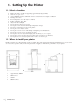
1. Setting Up the Printer 1.1. Select a Location · · · · · · · · · · · · · · · · Firm, level surface capable of supporting approximately 7kg (15.4 lbs). Clearance to open cover At least 100mm (4 inches) additional clearance on both sides for adequate ventilation Nearby power source Room temperature: 5° to 40° C (41° to 104° F) Relative humidity: 20 to 80% Away from direct sunlight Do not place the printer near a heater. Do not place it in a location with abrupt temperature changes.
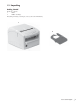
1.3 Unpacking Getting Started Check the contents: 1 Printer 2 Ribbon Cartridge If anything is missing or damaged, contact your dealer immediately. o425_02.jpg and o425_07.
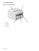
1.4 Installing the Printer Getting to Know the OKIPOS 425S 2 o425_02.
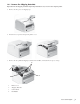
1.4.1 Remove the Shipping Restraints Important! Save the shipping restraints and packing materials in case you ever need to ship the printer. 1. Remove the five pieces of shipping tape. o425_01.jpg 2. Press the Cover open bar and open the printer cover. o425_03.jpg and o425_04.jpg 3. Remove the two printhead shipping restraints and red rubber, and detach the two pieces of tape. o425_05.
1.4.2 Setting the Interface Board Assembly 1.4.2.1 Setting the DIP Switches (RS-232C) A25001.doc Switch Setting DIP SW 1 2 3 4 D I P S W 1 D I P Function Selects the data bit length Selects between the presence and absence of parity bits.
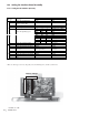
1.4.2.2 Installing the Interface Board Assembly (1) Insert the Interface Board Assembly in the direction of the arrow. o425_84.jpg (2) Secure the Interface Board Assembly with 2 screws. o425_28.
1.4.3 Connecting the Computer This printer supports either Parallel Interface or RS232C when the interface board is installed in the printer. To install the interface board, refer to Section 1.4.2.2. 1. Check to be sure that the printer’s power is OFF. 2. Connect the interface cable to the connector shown below. A) Parallel Interface B) Serial Interface o425_24.jpg and o425_82.jpg A B 3. Secure the connector by its latches or screws. 1.4.4 Connecting the Cash Drawer 1.
1.4.7 Installing the Ribbon Cartridge 1. 2. Make sure the printer is turned OFF. Press the Cover open bar and open the printer cover. o425_03.jpg and o425_04.jpg 3. Center the printhead. o425_06a.
4. Unpack the ribbon cartridge. Important! 1 o425_07.jpg Do NOT remove the ribbon shield from the ribbon! 2 3 1 2 3 5. Ribbon Shield Take-up Knob Grip Points Install the new ribbon cartridge. 1) Hold the ribbon cartridge as shown below. o425_08.jpg 2) Fit the grooves in the flat end of the cartridge over the posts on the ribbon plate.
3) Lower the front of the cartridge over the printhead until it snaps into place. o425_06.jpg 4) Turn the knob (1) in the direction of the arrow on the cartridge to take up the ribbon slack. o425_10.
1.5 Installing the Paper Paper Specifications Maximum thickness: 0.3 mm (0.012 inches) A25002.doc Media Type Width Length Weight Number of copies Thickness Cut-Sheet Paper (Sip/ Validation) Note 1 Single part (slip) 105 to 215.9mm (4.13” to 8.5”) 70 to 297mm (2.76” to 11.7”) 52 to 105 g/m2 (14 to 28lb) - 0.065 to 0.13 mm (0.0026” to 0.005”) Single part (validation) 105 to 215.9mm (4.13” to 8.5”) 70 to 297mm (2.76” to 11.
1.5.1 Roll paper 1.5.1.1 Adjusting the Roll Paper Guide 1. Adjust paper guide A (1) to the paper width. Paper width: 2.75 inches (69.5 mm) or 3.00 inches (76.2 mm) 1) When the printer is shipped, the paper width is set for wide roll paper (3 inch or 76.2 mm width) o425_10.jpg 1 2) To use narrow roll paper (2.73 inch or 69.5 mm width), hold up the roll paper guide and move it to the left to insert into the hole (1) at the lower frame. o425_10.
2. Adjust paper guide B to the paper width. 1) Pull out the set paper in arrow direction (a) and push it in the arrow direction (b) until it stops or until it touches the inside of the Guide-Rear edge (1). 2) Keeping the paper in position, turn the adjusting screw counter-clockwise to release the paper guide B (2) and adjust it to fit the roll paper edge. After paper width adjustment, turn the screw (3) clockwise to fasten the paper guide B. o425_10.
1.5.1.2 Loading the Roll Paper Use roll paper that matches the specifications. Note: The printer must be turned on before installing the roll paper. 1. Fold the paper so it is exactly straight and even (1), and will not tear off jaggedly (2). OP425_01b.eps 1 2. 3. 2 2 Turn on the printer and open the printer cover. Remove the rewinder. Insert the roll paper as shown below. o425_37.jpg 4.
5. When using the rewinder, follow the steps and the illustration below. 1) Turn the flange into the arrow direction and remove it. o425_93.jpg 2) Insert the tip of roll paper into the groove of the rewinder as shown in the detail figure. Then, turn the rewinder into the arrow direction to wind the roll paper around it 2 or 3 times. o425_94.jpg and o425_95.jpg a 3) Insert the flange into the rewinder (to the arrow direction 1) until it stops, then turn it into the arrow direction 2 to lock. o425_96.
1.5.1.3 Adjusting the Roll Paper Near End Sensing Position The paper near end detector detects when the paper is almost gone by measuring the diameter of the Roll paper. If you want to change the amount of paper remaining when the printer stops printing, follow the steps below to adjust the paper near end detector. Note: 1. 2 If the inner diameter of the Roll paper core is more than 26mm (1.02 inch), the Roll paper near end detector may not work properly. Open the printer cover and remove the rewinder.
1.5.2 Cut-Sheet Paper (Slip) 1.5.2.1 Loading the Cut-Sheet Paper (Slip) Use the paper that matches the specifications. Note: 1. 2. The printer must be turned on before loading the paper. Turn on the printer. Insert the paper as shown below, while butting the right edge of the paper against the paper guide. Note: When using a MICR-version machine, align the marks “䊱” and “䊲” as shown below and set the paper along the paper guide. o425_46.jpg 1 3.
1.5.3 Cut-Sheet Paper (Validation/Stub) 1.5.3.1 Loading the Cut-Sheet Paper (Validation/Stub) Use the paper that matches the specifications. Note: 1. 2. The printer must be turned on before loading the paper. Turn on the printer. With the right edge of the paper positioned at the “䊲” mark on the Cover Top, insert the paper. o425_48.jpg Note: To feed paper along the long edge, remove the Piece (1) on the left side of the printer cover and set the paper. o425_02.
How to remove the Piece 1. Press the Cover Open Bar and open the Printer Cover. CAUTION: Printhead may be very hot. o425_03.jpg and o425_04.jpg 2. Unlock the latch (1) of the Piece Cover B (2) and remove the Piece Cover B. o425_13.jpg 2 1 3. Remove Piece Cover A. o425_14.
4. Close Printer Cover. * Paper has been set for long-edge printing. o425_49.jpg * Store the removed Piece in a safe place so that you will not lose it.
1.5.4 Sprocket Paper (Tractor) 1.5.4.1 Loading the Sprocket Paper (Tractor) Use the paper that matches the specifications. Note: The printer must be turned off before inserting the tractor. 1. Turn off the printer. Move the Paper Guide all the way to the right. Pull the hooks (1) on the tractor cover (2) in the arrow direction and remove the tractor cover. o425_02.jpg 1 2. Insert the tractor as shown below, and lock the tractor lock lever (1). o425_16.
3. Set the tractor lever (1) in the direction of the arrow. o425_18.jpg 1 4. 5. Turn on the printer. Pull up on the lock levers (1) and open the tractor covers (2), then move the right tractor over to fit the width of the paper. Center the support (3) between the tractors. o425_50.jpg 3 4 2 1 6. Place the first two holes in the paper over the tractor pins (4) on either side and close the tractor covers. o425_51.
7. Move the left tractor to align the edge of the paper with the appropriate reference mark (!), and push back the right lock lever (2). o425_52.jpg 2 8. Fine-tune the position of the right tractor to center the holes in the paper on the pins, and push back the left lock lever (1). o425_52.
9. Printer feeds the paper into the printer when your computer sends data. 10. Preparation 1) Position the printer at the front edge of the support (this promotes the unrestricted flow of paper into the printer), then place a stack of Sprocket (Tractor) Paper below the printer. 2) The standard height of desks on which the printer is installed should be 75cm. Paper should be loaded in parallel with the paper running path wherever possible. The deviation to right and left should be 5cm or less.
2. Using the Printer 2.1 Operation Panel Functions Note OEM Fiscal Type: The operation panel is under the control of the fiscal control PCB. Consequently, the fiscal control PCB should be removed before self tests. Alternatively, disconnecting the cable from the main control PCB is acceptable. Operation Panel Specification o425_20.
2.1.1 Switching Functions A25046.doc No. Switch Function in Modes other than Tractor In Receipt Mode: Feeds Receipt paper for the specified length (10/6”) In Slip Mode: Ejects a fed slip paper In Validation Mode: Disabled *Printing will not be started.
2.1.2 LED Function A25004.doc No.
2.2 Local Functions Note OEM Fiscal Type : This section describes local maintenance capabilities under the control of the printer block. The fiscal control PCB should be removed before the functions are performed. 2.2.
2.2.2 Starting A25047.doc No.
2.3 Menu Function (Receipt) Overview The menu function is the local function that sets each mode to control the printer and adjust it. This mode has the following items, saved in the E2P-ROM. This information is printed only when the menu mode is activated at Power On, and the information can be overwritten from the operator panel. Menu Print is printed in Receipt Mode. The menu determines the initialization state of each mode. 2.3.1 OEM — Standard Model A25006.doc No.
2.3.2 OKI — Standard Model A25007.doc No. 1 Item Auto Cutter Unit Function Selects Auto Cutter Unit Installed/Not Installed Sets Yes No Yes(CMC-7) Yes(E-13B) O No 0.25mm Right 0.20mm Right 0.15mm Right 0.10mm Right 0.05mm Right 0 0.05mm Left 0.10mm Left 0.15mm Left 0.20mm Left 0.25mm Left -1.75mm ~ +1.75mm *Can be set in the 0.35mm unit *Default value: 0 mm -1.75mm ~ +1.75mm *Can be set in the 0.
2.3.3 How to Operate Start To start the Menu Mode, turn the printer on while holding down SW2 + SW1. When the printer’s initialization ends correctly, the printer prints the title “Menu Print” and all the menu items and set values. Then, the printer line-feeds until the print result goes beyond the Manual Cutter position, prints the item/set value immediately after “Menu Print,” then waits for a switch to be pressed. Operation The switch functions during the menu mode are as follows: A25008.
2.4 Hex Dump Function (Receipt) This function converts received data, as it is, to character codes, and prints it in the Receipt mode. The printed contents are as follows: Upon receiving one byte, the printer divides it into three characters, High-nibble, Low-nibble and a space. Regarding these as 1 block, the printer prints 8 blocks in one line, then, prints the same data in the character format. Upon entering the HEX dump mode, the printer prints “Hex Data Dump”. (Title printing) 2.4.
2.5 Using the MICR Reader (Option) If your printer has the factory installed optional MICR (Magnetic Ink Character Recognition) reader that enables the printer to read and process MICR characters on personal checks, read this section. Note 1: If Cut-sheet Paper or Sprocket Paper has been loaded, eject it before you use the MICR feature. This does not apply to the Roll Paper.
How to use the MICR Reader 1. Send the command “FS a 0 n” from the host computer. Then the printer shifts to the MICR Mode and waits for the Check Sheet to be inserted. LED3 blinks slowly in orange (repeats 1 sec ON, 1 sec OFF). 2. Insert the Check Sheet with its magnetic ink print surface up and the magnetic ink print area to the right side of the direction of insertion, butting it against the right side of the printer. The printer feeds the Check Sheet and reads at the same time. 3.
2.6 MICR Read Test (Receipt) This function performs MICR read and prints that result on the receipt paper. Effective only when the MICR unit is installed and “MICR Unit = Yes(CMC-7)” or “MICR Unit = Yes(E-13B)” is set in the menu. (1) How to start Turn the power on while holding down SW2 + SW3. (2) How to exit Turn the power off. (3) Contents of the test (a) When this mode is started, the printer enters Wait for MICR Insertion state. (b) Insert MICR card and perform MICR read.
(4) Contents printed When Read is OK: (a) Prints “Read OK.” (b) Prints the MICR read results in HEX dump. (“XX XX ...... XX” + ASCII: 1 line contains 8 byte information) When Read is NG: (a) Prints “Read NG.” (b) Prints the MICR read results (Return Code (1 byte) and read data) in HEX dump. (“XX XX ...... XX” + ASCII: 1 line contains 8 byte information) • Regarding MICR Read result, Return Code (1 byte) and Read Data are printed. When the Return Code is 30H (“No errors”), it is assumed as “Read OK.
2.7 Rewinder Winding Evaluation Continuous Print Test (Receipt) This function performs print/platen switch continuous test to evaluate the rewinder winding performance. (1) How to start Turn the power on while holding down SW3 + SW1 + SW4. (2) How to exit Turn the power off. • During test printing, if you press SW1, printing suspends. If you press SW1 again, printing resumes.
3. Maintenance 3.1 Replacing the Ribbon Cartridge When printing becomes light, replace the Ribbon Cartridge, following the procedure shown below: 1. Make sure the printer is turned OFF. 2. Press the Cover open bar and open the printer cover. o425_03.jpg and o425_04.jpg 3. Center the printhead. o425_06a.
4. Swing the front of the cartridge up off the printhead, then lift the cartridge out and discard it. Caution! The printhead may be HOT! o425_06.jpg 5. Unpack the ribbon cartridge. Important! Do NOT remove the ribbon shield (1) from the ribbon! 1 o425_07.jpg 2 3 6. 1 Ribbon Shield 2 Take-up Knob 3 Grip Points Install the new ribbon cartridge. 1) Hold the ribbon cartridge as shown below. o425_08.jpg 2) Fit the grooves in the flat end of the cartridge over the posts on the ribbon plate.
3) Lower the front of the cartridge over the printhead until it snaps into place. o425_06.jpg and o425_09.jpg 4) Turn the knob (1) in the direction of the arrow on the cartridge to take up the ribbon slack. o425_10.
3.2 Replacing the Roll Paper When the Roll is used up, load a new one, following the procedure shown below. 1. Press Form Feed switch (1) and eject all the Receipt Paper (2). o425_54.jpg 2 1 2. Press the Cover Open Bar and open the Printer Cover. * Caution! The printhead may be HOT! o425_03.jpg and o425_04.
3. Remove the paper roll on the rewinder, following the procedure below. (1) Remove the rewinder (1) from the printer (2). o425_37.jpg 1 2 (2) Rotate the flange (2) in the direction shown below and remove it from the rewinder (1). Note 1: Rotation direction of the flange varies depending on the width of the Roll Paper. Arrow 3: Wide Roll Paper (Width: 76.2 mm) Arrow 4: Narrow Roll Paper (Width: 69.5 mm) Note 2: When a spacer is installed, remove the spacer along with the flange. o425_44.
3.3 Clearing Paper Jams When Roll Paper gets jammed, remove the paper, following the procedure shown below: 1. Press Cover Open Bar and open the printer cover. * Print head may be very hot. Exercise caution. o425_03.jpg and o425_04.jpg 2. Remove the rewinder and cut the Roll Paper (1) at the location (2) shown below. o425_102.
3. Press the two levers (1) on either side at the same time as shown, lift the plate assembly and gently pull out the jammed paper in the direction of the arrow. Note: Be careful not to leave small pieces of paper. o425_103.jpg and o425_104.jpg 1 4. 1 Load a new paper roll. For the procedure to load Roll Paper, refer to Section 1.5.2. Note: Before loading Roll Paper, press down on the two levers (1) to close the plate assembly securely. o425_105.
Cut-Sheet Paper When cut-sheet paper gets jammed, remove the paper, following the procedure shown below: 1. Press the Cover Open Bar and open the printer cover * Print head may be hot. Exercise caution. o425_03.jpg and o425_04.jpg 2. Slowly pull out the paper upward or toward you while pulling the lever (1) [marked “PULL”] toward you. Note: Be careful not to leave small pieces of paper behind. o425_56.
Sprocket Paper When sprocket paper gets jammed, remove the paper, following the procedure shown below. 1. Open the Tractor Cover (1) and cut the sprocket paper at the perforation (2). o425_57.jpg 2 1 2. Press the Cover Open Bar and open the printer cover o425_03.jpg and o425_04.jpg 3. Slowly pull out the paper upward or toward you while pulling the lever (1) [marked “PULL”] toward you. Note: Be careful not to leave small pieces of paper behind. o425_80.
4. Troubleshooting and Repair 4.1 Alarm Indication for a Failure When a failure occurs, the printer indicates its contents with LED1 lamp on the operation panel, which blinks in different ways depending on the failure type. Note: OEM Fiscal Type: The alarm indication works only when the Fiscal Control PCB is not mounted. o425_20.
4.1.1 Details of Alarm Indications Table411.doc No. of times LED 1 blinks 1 2 3 4 5 6 Malfunction contents 8 Platen Switching Alarm 9 10 11 12 13 Head A/D Error WDT (F/T Control) NMI (F/W Control) BRK (F/W Control) MICR Unit Error (only with MICR type) 14 Interface PCB Error (only OKI standard type) Program ROM Alarm EEPROM Alarm Internal RAM Alarm External RAM Alarm Homing Alarm Spacing Alarm OP425_04.
4.1.2 LED Indication Table412.doc No. 1 LED LED 1 (ERROR) 2 LED 2 (STATUS) Red Orange ON [Recoverable Alarms] Slip Load Alarm → Slip paper was not loaded correctly. Remove it and reload it. Slip Exit Alarm → Slip paper did not exit correctly. Remove the Slip paper. Auto Loading Alarm → Sprocket paper was not loaded correctly. Set it at the correct position of the Tractor and do the loading operation again. Auto Parking Alarm → Sprocket paper did not eject correctly. Do the parking operation again.
5. Specifications 5.1 Introduction 5.1.1 Scope of Application This specification applies to OKIPOS 425S/425S/425SF, a 9-pin type serial dot impact printer. This device is a desk-top serial dot impact printer, used exclusively as the output device for POS (Point-of-sales) system. • OKIPOS 425S: OKI Single Standard Version • 425S: OEM Single Standard Version • 425SF: OEM Single Fiscal Version 5.1.
Options 1 Front Tractor: User Option o425_26.jpg 2 Parallel Interface: Dealer Option (OKI/OEM Standard Type) o425_23.jpg 3 RS-232C Interface: Dealer Option (OKI Standard Type) o425_81.jpg Note Only one interface option can be installed.
5.1.3 Configuration Standard Printer Configuration 1 Printer Cover 2 Control Panel 3 Paper Guide 4 Cover Open Bar 5 ON/OFF Switch o425_02.
5.2 General Specifications 5.2.1 Power Requirements 1 2 Input power Single-phase AC Voltage: Universal 120VAC+15% – 230VAC+15% Frequency: 50/60Hz +2% Power consumption (without Fiscal Control PCB) Local Test : Max. 40W (Local Printing) Idle: Max. 15W 5.2.2 Environmental Conditions 1 Ambient temperature and relative humidity Operating Non-operating Temperature 41 to 104 (5 to 40) Relative 20 to 80 Humidity Unit 32 to 109.4 (0 to 43) 10 to 90 °F (°C) %RH Avoid condensation at all times. 5.2.
5.3 Communication Interface Specifications 5.3.1 Parallel Interface (OKI/OEM Standard Type) 1 Interface Spec (Between centronics connector and host PC) Parallel interface signal part (IEEE-1284 parallel equivalent) Centronics Connector Pin Assignment signal A25012.doc Pin No.
5.3.2 RS-232C Interface (OKI Standard Type) 1 Interface signals A25013.doc Pin No.
5.3.3 Cash Drawer connector (OKI Standard Type) 1 Cash Drawer Connector Signals A25014.doc Pin No. 1 2 3 4 5 6 Signal Name FG CASHDV1 CASHST-N +24V CASHDV2 EL Note: Pin arrangement OP425_07.
5.3.4 Customer Display connector (OKI Standard RS-232C Interface Type) 1 Customer Display Connector Signals A25015.doc Pin No. 1 2 3 4 5 6 7 8 Note Signal Name FG NC TD DTR DSR EL +24V EP Direction To Customer Display To Customer Display From Customer Display To Customer Display - Function Frame ground Not Connected Data to Customer Display +12VDC Power supply Indicates that data can be sent Signal ground +24VDC power supply Power ground Pin arrangement OP425_08.
5.4 Physical Characteristics 5.4.1 Printhead Print method: Number of dot wires: Dot wire diameter: Impact dot matrix 9 wires 0.34 mm (0.013") 5.4.2 Printer 1 Outside dimensions (without Tractor) 265 mm (10.43") (W) x 218 mm (8.58") (H) x 337 mm (13.27") (D) 218mm (8.58inch) OP425_09b.eps 265mm (10.43inch) 2 64 | 25.5mm (1inch) 337mm (13.27inch) Outside dimensions (with Tractor) 265 mm (10.43") (W) x 218 mm (8.58") (H) x 422 mm (16.
5.5 Logical Characteristics 5.5.1 Print Direction Bidirectional, unidirectional printing Short-line-seeking printing 5.5.2 Selectable Character Pitches Character width A25016.doc Selected font HSD Utility HSD (*1) 20 CPI 16.4 CPI 26.7 CPI Regular size 0.05 inch 0.061 inch 0.037 inch 1.27 mm 1.55 mm 0.95 mm 10 CPI 8.2 CPI 13.3 CPI Double wide size 0.1 inch 0.122 inch 0.075 inch 2.54 mm 3.10 mm 1.91 mm (*) OEM Type: Cut Sheet or Sprocket Paper (Tractor) mode only Utility (*1) 21.8 CPI 0.046 inch 1.
5.5.4 Font Size/Cell Size A25019.doc Font type Font size (H x V) Cell size (H x V) CPI HSD 7 x 7 dots 9 x 9 dots 20 (26.7 *1) Utility 9 x 7 dots 11 x 9 dots 16.4 (21.8 *1) (*1) OEM Type is Select Cut Sheet or Sprocket paper (Tractor) mode only. Apply narrow size roll paper. 5.5.5 Line Feed Pitches 6 LPI [4.23 mm (0.167")] OEM Type: A variable line feed pitch of n/216 inch (integer n: 0 < n < 255) can also be specified.
5.7 Media Specifications 5.7.1 Cut-Sheet Paper (Slip/Validation) Paper Width: 105 to 215.9 mm (4.13" to 8.5") Paper Length: 70 to 297 mm (2.76" to 11.7") Single part (Slip) Weight: 52 to 105 g/m2 (14 to 28 lb) Thickness: 0.065 to 0.13 mm (0.0026" to 0.005") Single part (Validation) Weight: 65 to 81g/m2 (17 to 21 lb) Thickness: 0.08 to 0.1 mm (0.0031" to 0.0039") Multipart-carbon lined or pressure sensitive Weight: 34 to 40g/m2 (9 to 11 lb) Number of copies: Original plus 4 copies Thickness: 0.3 mm max. (0.
5.7.4 Sprocket Paper (Tractor) Paper Width: 76.2 to 215.9 mm (3" to 8.5") Paper Length: 76.2 to 355.6 mm (3" to 14") Single part Weight: 52 to 81g/m2 (14 to 21 lb) Thickness: 0.065 to 0.1 mm (0.0026" to 0.0039") Multipart-carbon lined or pressure sensitive Weight: 34 to 40g/m2 (9 to 11 lb) Number of copies: Original plus 3 copies Thickness: 0.27 mm max. (0.01" max) Multipart-interleaf Weight: 38 to 45g/m2 (10 to 12 lb) [Carbon: 34g/m2 (9 lb)] Number of copies: Original plus 2 copies Thickness: 0.27 mm max.
5.7.5 Appendix: Media Specifications 5.7.5.1. Cut-Sheet Paper (Slip/Validation) 5.7.5.1.1. Paper Size and Printing Area 1 Single-part Paper OP425_10.eps 3 4 1 6 2 5 1 2 3 4 5 6 Base line First character position Paper inserting direction Against the perpendicular to the Base line Printing area + 0.2mm or less Standard media are in A5 and B5 sizes. A25022.
2 Counterfoil and Stub OP425_11.eps 1 2 3 1 2 3 Printing area Stub Inserting direction A25023.doc Symbol W L A B C D Designation Paper width Paper length Print starting position Left margin Right margin Printing area width Standard Value 70mm (2.76 inch) or more 40mm (1.57 inch) or more 18mm (0.7 inch) or less 2.54mm (0.1 inch) or more 2.54mm (0.1 inch) Max 160.02mm (6.3 inch) Note 1 To feed paper, insert a paper from the top side of the device and keep holding it until printing ends.
3 Multi-part Paper The standard multi-part paper is the one whose top edge is pasted. OP425_13.eps 5 1 7 2 8 3 6 4 1 2 3 4 Pasted securely (1mm) Base line First character position Printing surface 5 6 7 8 Paper inserting direction Printing area Against the perpendicular to the Base line + 0.2mm or less Standard media are in A5 and B5 sizes. A25024.
5.7.5.1.2 Paper Quality The paper in the following quality may be used. A25025.doc Type Single-part paper and Stub Multi-part paper 1 2 Paper Quality High quality paper Pressure-sensitive paper, Carbon-lined paper Paper smoothness must be 90 ~ 7 sec. for Beek and 75 ~ 300 sec. for Sheffield. If you use paper other than that specified, test it to verify that it prints without problems. 5.7.5.1.3 Paper Weight and Maximum Duplicating Quantity The weight of paper usable for printing and max.
5.7.5.1.5 Binding Holes Do not use a paper with punched holes. It may invalidate your warranty. If you choose to use punched paper, be sure to test it thoroughly. Follow these guidelines: 1 Do not print within 5 mm of the hole center. 2 Make sure that paper dust is not left on the paper. 3 If a hole passes over the paper sensor, a false paper end signal may result. 4 Make sure that the edges of holes are even with the paper surface. If they stick up, the printhead may not move smoothly.
5.7.5.1.6 Perforated Lines Do not use paper with perforations. It may invalidate your warranty. If you choose to use perforated paper, be sure to test it thoroughly. Follow these guidelines: 1 The specification of a perforated line corresponds to that of a perforated line on Sprocket Paper. 2 Do not print within the shaded area adjoining the perforations. 3 An example of a perforated sheet is shown in the figure below. op425_16.
5.7.5.1.7 Provisions on Fold, Bend and Curl on Cut-sheet Paper Paper is apt to sustain bends, cambers or curls resulting from manual handling, carrying, stacking, storing conditions, etc. Therefore, before printing, check and adjust paper in accordance with the provisions below to eliminate paper feed problems. Do not use paper that does not meet the specifications outlined here: it may cause paper feed problems. Problems caused by using non-specified paper are not covered under warranty.
5.7.5.2. Roll paper 5.7.5.2.1 Paper size and Printing area Multi-part Paper OP425_19b.eps 2 1 3 1 First character position 2 Cutting position (for manual cutting) 3 Printing area A25048.doc Symbol W φA φB C D E F 76 | Designation Roll paper width Roll paper outside diameter Core inside diameter Left margin Right margin Printing area width Top margin OKIPOS 425S Standard Value 69.5/76.2 mm (2.73/3 inch) +0.5mm (0.02 inch) φ101.6mm (4 inch) or less 10mm (0.4 inch) or more 2.54 mm (0.
5.7.5.2.2 Paper Quality Paper of the following quality may be used. A25028.doc Type Single-part paper 1 2 Paper Quality High quality paper Paper smoothness must be 90 ~ 7 sec. for Beek and 75 ~ 300 sec. for Sheffield. If you use paper other than that specified here, test it to verify that it prints without problems. 5.7.5.2.3 Paper Weight The weight of paper usable for printing . A25029.doc Type Paper Quality Weight Max.
5.7.5.3. Sprocket Paper (Tractor) 5.7.5.3.1 Paper size and Printing area OP425_20.eps 6 4 3 1 2 5 1 Printing area 2 Printable area 3 First character position 4 Paper inserting direction 5 Unit: mm 6 Maximum 160.02 The specification for the printable area differs from that for the printing area. A25030.
Symbol W L Designation Paper width Paper length A B C D E F G H I J Heading position st Top margin (on the 1 page) Bottom margin, recommended Bottom margin, printable Top margin, recommended Top margin, printable Bottom margin, recommended Bottom margin, printable Unprintable left margin Unprintable right margin Standard Value 76.2~215.9mm (3~8.5 inch) 76.2~355.6mm (3~14 inch) The length must be the one obtained via multiplying 25.4mm (1 inch) by an integer 10.31mm (0.41 inch) 25.4mm (1 inch) 19.
5.7.5.3.2 Paper Quality Paper of the following quality may be used. A25031.doc Type Single-part paper Multi-part paper Paper Quality High quality paper (1) Pressure-sensitive paper, Carbon-lined paper or Interleaved paper Note 1 Interleaved paper is a multi-part paper with carbons inserted between copies. 1 2 Paper smoothness must be 90 ~ 7 sec. for Beek and 75 ~ 300 sec. for Sheffield. If you use paper other than that specified here, test it to verify that it prints without problems. 5.7.5.3.
5.7.5.3.4 Fixing Method of Multi-part Paper Joint The joint fixing method for a multi-part paper shall be spot-pasting, line-pasting or crimping. Spot pasting is the proper precaution against position deviation made when piling sheet tiers. Crimping may cause position deviation of approx 3 mm. Metal staples must not be used. 1 Spot Pasting a Spot pasting must be conducted on both right/left sides. Paper which is pasted on only one side is not accepted.
3 Crimping a Crimp paper on both right/left sides. b Apply crimping from the front surface, making no protrusion on the surface. c All the sheets must be engaged securely with each other at the crimp position free of lifting. d Use a double-type crimp and apply crimping in the direction to produce the crimped mark horizontal to the paper right/left edges. e Press paper after crimping to eliminate lifting. OP425_23.eps 2 3 4 6 5 1 7 1 2 3 4 5 6 7 8 9 10 82 | 50.
5.7.5.3.5 Rising in Horizontal Perforated Line Protrusions in a horizontal perforated line may result in poor print quality, unstable paper feeding or frequent paper jam. Therefore, the rising height must be kept within 1mm. OP425_24.eps 2 1 1 2 1 2 Horizontal perforated line Within 1mm 5.7.5.3.6 Position Deviation of Sprocket Holes Deviation of the sprocket hole positions may be caused when each copy or tier is piled to produce multi-part paper. Use multi-part paper whose sprocket deviation is 0.
5.7.5.3.7 Binding Holes Do not use a paper with punched holes. It may invalidate your warranty. If you choose to use punched paper, be sure to test it thoroughly. Follow these guidelines: 1 Do not print within 5 mm of the hole center. 2 Make sure that paper dust is not left on the paper. 3 If a hole passes over the paper sensor, a false paper end signal may result. 4 Make sure that the edges of holes are even with the paper surface. If they stick up, the printhead may not move smoothly.
5.7.5.3.8 Corner Cut Do not use paper with corner cuts. It may invalidate your warranty. If you choose to use corner cut paper, be sure to test it thoroughly. Follow these guidelines: 1 Do not print within the shaded area adjoining a corner cut. 2 Make sure that paper dust is not left on the paper. 3 The perforation of the vertical/horizontal perforated line must not intersect with the corner cut to prevent the paper from peeling off.
5.7.5.3.9 Wrinkle, Pleat and Swell Use paper, which has been folded zigzag on horizontal perforated lines, free of wrinkles and pleats. Newly unpacked paper often has wrinkles or pleats on the first and last pages. Please eliminate pages having wrinkles and pleats before printing. Do not utilize paper whose folding position inflates as illustrated in the fig below, because it may cause malfunction in paper feed. OP425_28.eps and OP425_29.
5.7.5.4. MICR (only with MICR Type) 5.7.5.4.1 Paper Size and Scanning Area OP425_30.eps 1 2 1 2 Paper inserting direction Scanning Area A25033.doc Symbol W L A B C D E Designation Paper width Paper length Scanning area - Standard Value 76~78mm (2.99~3.07 inch) 174~176mm (6.85~6.93 inch) 4.8mm (0.19 inch) 6.4mm (0.25 inch) 4.8mm (0.19 inch) 6.35mm (1/4 inch) or more 50mm (1.97 inch) or more 5.7.5.4.2 Paper Weight The weight of paper usable for Scanning A25034.
5.8 Paper Feed Specifications 5.8.1 Paper feed methods/Paths a b c Friction feed Friction feed Push tractor feed (Front path) For Cut-sheet paper For Roll paper For Sprocket paper (Tractor) 5.8.2 Paper Positioning Restrictions OP425_31.eps 2 1 3 4 6 5 1 2 3 4 5 6 Cut-sheet paper (slip) Roll paper Sprocket paper (Tractor) Printing position on the first line Printing position on the last line Cut-sheet paper (Counterfoil, Stub) 5.8.3 Paper Tear-off Roll paper The paper can be torn off 41.69mm (1.
5.9 MICR Specifications (Only with MICR type) 5.9.1 Available Fonts E-13B and CMC7 (can be selected command) 5.9.2 Scanning Speed 9.2 inches / sec 5.9.3 Recognition Rating 95% or more at 25°C Rating = ([total checks - number misread or not identified] / total checks) x 100 Check paper tested is OKI recognized check paper 5.9.4 Reliability Life: 240,000 passes Passes: reading and printing on U.S. personal check 152mm long 5.9.5 Readable Area Conforms to the APPENDIX B MEDIA SPECIFICATIONS 4 5.9.
5.10 Ribbon Specifications Genuine Oki Data cartridge ribbon Ink color: Black Ribbon life: Approximately 3 million characters (when 1 character = 14 dots) 5.11 Reliability 1 2 3 4 90 | MTBF (mean time between failures) 10,000 hours of power-on time at 25% duty cycle. Page density: 35% Printhead life 200 million characters (average) in Utility Print Quality mode. Printer life 5 years of power-on time at 10 hours/day, 365 days/year. MTTR (mean time to repair) 15 minutes, major sub-assembly level.
6. Command Description 6.1 Control Code List 6.1.1 OEM — Standard Model 6.1.1.1 Function Code 1 List of Function Codes A25037.doc No.
6.1.1.2 ESC Sequence 1 Command recognition A code subsequent to an ESC code is handled as a 7-bit code. (MSB=0) An ESC code that is followed by a functional code (except ESC CR) is handled as a single functional code. If the ESC codes follow each other, they are treated as one ESC code. Example: ESC ESC 2 is treated as ESC 2. 2 ESC sequence list A25038.doc 92 | No.
6.1.1.3 GS sequence 1 Command recognition GS codes in combination are handled the same way that ESC codes are handled. 2 GS Sequence table A25039.doc No. 1 HEX 1D 45 Command Sequence GS E n 2 1D 76 GS v n Functions To select print speed and printhead current flow time. To select Validation inserting position Print Start X X 6.1.1.4 US Sequence A25038a.doc No.
6.1.2 OKI Standard Model 6.1.2.1 Function Code 1 List of Function Codes A25040.doc No.
6.1.2.2 ESC Sequence 1 Command recognition ESC codes in combination are handled the same way that DLE codes are handled. 2 ESC sequence list A25041.doc and A25041b.doc in series No.
* 46 47 1B 6D 1B 70 ESC m ESC p m t1 t2 48 49 50 51 52 1B 74 1B 75 1B 76 1B 77 1B 7A ESC t n ESC u n ESC v ESC w n ESC z n 53 1B 10 41 54 1B 10 42 ESC DLE A Pno N1…N8 ESC DLE B Pno Pm DATA Partial cut (keeping one point uncut) Generates designated pulse (Open Cash Drawer) Selects character code table Sends peripheral device status Sends paper sensor status Sets/resets Double Height print Designates/cancels Receipt+Journal same data print Selects and sets the barcode type and size Prints barcode
6.1.2.3 FS Sequence 1 Command recognition FS codes in combination are handled the same way that DLE codes are handled. 2 FS Sequence table A25042.doc No. HEX Command Sequence Functions 1 2 3 4 1C 61 30 1C 61 31 1C 61 32 1C 62 FS a 0 n FS a 1 FS a 2 FS b Reads Check paper Loads Check paper to the print start position Ejects Check paper Requests for resending a result of reading Check paper Print Start X X X X 6.1.2.
6.2 Character Set 6.2.1 Code table (OEM — Standard Type) The character code tables follow. 6.2.1.1 USA OP425_03.tif 1 2 3 4 98 | 0xH and 1xH are Control Code areas. If a code received is other than a control code in 0xH and 1xH, it is ignored. The above table assumes international character set is set to “American.” The blank space (20H, 7FH, FFH) indicates a space code.
6.2.1.2 Canada-French OP425_04.tif 1 2 3 4 0xH and 1xH are Control Code areas. If a code received is other than a control code in 0xH and 1xH, it is ignored. The above table assumes international character set is set to “American.” The blank space (20H, 7FH, FFH) indicates a space code.
6.2.1.3 Multilingual OP425_05.tif 1 2 3 4 100 | 0xH and 1xH are Control Code areas. If a code received is other than a control code in 0xH and 1xH, it is ignored. The above table assumes international character set is set to “American.” The blank space (20H, 7FH, FFH) indicates a space code.
6.2.1.4 Portugal OP425_06.tif 1 2 3 4 0xH and 1xH are Control Code areas. If a code received is other than a control code in 0xH and 1xH, it is ignored. The above table assumes international character set is set to “American.” The blank space (20H, 7FH, FFH) indicates a space code.
6.2.1.5 Norway OP425_07.tif 1 2 3 4 102 | 0xH and 1xH are Control Code areas. If a code received is other than a control code in 0xH and 1xH, it is ignored. The above table assumes international character set is set to “American.” The blank space (20H, 7FH, FFH) indicates a space code.
6.2.1.6 BRASCII OP425_08.tif 1 2 3 4 5 0xH and 1xH are Control Code areas. If a code received is other than a control code in 0xH and 1xH, it is ignored. The above table assumes international character set is set to “American.” The blank space (20H, 7FH, A0H) indicates a space code. 8xH and 9xH are ignored.
6.2.1.7 Abicomp OP425_09.tif 1 2 3 4 5 104 | 0xH and 1xH are Control Code areas. If a code received is other than a control code in 0xH and 1xH, it is ignored. The above table assumes international character set is set to “American.” The blank space (20H, 7FH, A0H) indicates a space code. 8xH, 9xH, ExH, and FxH are ignored.
6.2.1.8 Multilingual 858 OP425_10.tif 1 2 3 4 0xH and 1xH are Control Code areas. If a code received is other than a control code in 0xH and 1xH, it is ignored. The above table assumes international character set is set to “American.” The blank space (20H, 7FH, FFH) indicates a space code.
6.2.1.9 ISO 8859/15 OP425_11.tif 1 2 3 4 5 106 | 0xH and 1xH are Control Code areas. If a code received is other than a control code in 0xH and 1xH, it is ignored. The above table assumes international character set is set to “American.” The blank space (20H, 7FH, A0H) indicates a space code. 8xH and 9xH are ignored.
6.2.1.10 International character set table A25044.
6.2.2 Code table (OKI — Standard Type) The character code tables follow. 6.2.2.1 USA OP425_12.tif 1 2 3 4 108 | 0xH and 1xH are Control Code areas. If a code received is other than a control code in 0xH and 1xH, it is ignored. The above table assumes international character set is set to “American.” The blank space (20H, 7FH, FFH) indicates a space code.
6.2.2.2 Canada-French OP425_13.tif 1 2 3 4 0xH and 1xH are Control Code areas. If a code received is other than a control code in 0xH and 1xH, it is ignored. The above table assumes international character set is set to “American.” The blank space (20H, 7FH, FFH) indicates a space code.
6.2.2.3 Multilingual OP425_14.tif 1 2 3 4 110 | 0xH and 1xH are Control Code areas. If a code received is other than a control code in 0xH and 1xH, it is ignored. The above table assumes international character set is set to “American.” The blank space (20H, 7FH, FFH) indicates a space code.
6.2.2.4 Portugal OP425_15.tif 1 2 3 4 0xH and 1xH are Control Code areas. If a code received is other than a control code in 0xH and 1xH, it is ignored. The above table assumes international character set is set to “American.” The blank space (20H, 7FH, FFH) indicates a space code.
6.2.2.5 Norway OP425_16.tif 1 2 3 4 112 | 0xH and 1xH are Control Code areas. If a code received is other than a control code in 0xH and 1xH, it is ignored. The above table assumes international character set is set to “American.” The blank space (20H, 7FH, FFH) indicates a space code.
6.2.2.6 BRASCII OP425_17.tif 1 2 3 4 5 0xH and 1xH are Control Code areas. If a code received is other than a control code in 0xH and 1xH, it is ignored. The above table assumes international character set is set to “American.” The blank space (20H, 7FH, A0H) indicates a space code. 8xH and 9xH are ignored.
6.2.2.7 Abicomp OP425_18.tif 1 2 3 4 5 114 | 0xH and 1xH are Control Code areas. If a code received is other than a control code in 0xH and 1xH, it is ignored. The above table assumes international character set is set to “American.” The blank space (20H, 7FH, A0H) indicates a space code. 8xH, 9xH, ExH, and FxH are ignored.
6.2.2.8 Multilingual 858 OP425_19.tif 1 2 3 4 0xH and 1xH are Control Code areas. If a code received is other than a control code in 0xH and 1xH, it is ignored. The above table assumes international character set is set to “American.” The blank space (20H, 7FH, FFH) indicates a space code.
6.2.2.9 ISO 8859/15 OP425_20.tif 1 2 3 4 5 116 | 0xH and 1xH are Control Code areas. If a code received is other than a control code in 0xH and 1xH, it is ignored. The above table assumes international character set is set to “American.” The blank space (20H, 7FH, A0H) indicates a space code. 8xH and 9xH are ignored.
6.2.2.10 International character set table A25045.
7. Using the Unitool Printer Driver 7.1 Setting Slip Paper in the Paper Tray This section describes the method to set Slip paper in the input bin. With this printer, the position of the Paper Guide can be adjusted sideways, enabling you to change the paper setting position. If you use this printer driver, however, follow the procedure below when determining the right/left margins for paper and the position to set the Slip paper. Some examples and cautionary notes for use are provided below.
7.1.1 Using Registered Paper Icons 1 Paper width is 190.5 mm (7.5") or more and up to 215.9 mm (8.5") inclusive. O425_108.jpg 1 2 3 4 5 6 7 8 9 10 11 Printing area Left Margin 27.94mm (1.1 inch) Right Margin 27.94mm (1.1 inch) Printable Maximum Width 160.02mm (6.3 inch) Slip Tray Left Side Paper Guide Slip Tray Right Side Left Margin 2.54mm (0.1 inch) Paper Width = 215.9 mm (8.5") 190.5 mm (7.5") < Paper Width < 215.9 mm (8.5") Paper Width = 190.5 mm (7.
For paper that is 190.5 mm (7.5") or more and less than 215.9 mm (8.5"), slide the Paper Guide toward the left as needed so that the entire printing area on the paper shifts toward the right, as illustrated below. O425_109.jpg 1 2 3 4 5 6 7 8 120 | Printing area Printable Maximum Width 160.02mm (6.3 inch) Right Margin 27.94mm (1.1 inch) Slip Tray Left Side Paper Guide Slip Tray Right Side Normal operation Paper Guide shifted toward the left.
2 Paper Width is less than 190.5 mm (7.5"). The printing area, when printing paper that is less than 190.5mm (7.5") in width, is illustrated below. For paper 190.5 mm (7.5") or more and less than 215.9 mm (8.5"), slide the Paper Guide toward the left as needed so that the entire printing area on the paper shifts toward the right. O425_110.jpg 1 2 3 4 5 6 Printing area Slip Tray Left Side Printable Maximum Width 160.02mm (6.3 inch) Right Margin 27.94mm (1.
7.1.2 Using Custom Size Custom Size is variable in width in the range of 187.96 mm (7.4") - 215.9 mm (8.5"). 7.1.2.1 Using Paper Size that is less than 187.96 mm (7.4") in Width To adjust the left and right margins and create data for a paper size you want to use, follow the procedure below. 1 Set the length of paper to use in the Custom Size Setup dialog. (The width is fixed at 187.96 mm [7.4"].) 2 Open an application you want to use and customize your paper at Custom Size on the Page Setup menu.
Set the right margin at 27.94 mm (1.1") (Printing disabled area 25.4 mm [1.0"] + Slip paper’s minimum right margin 2.54 mm [0.1"]) or more. Image of actual printing area O425_112.jpg 1 2 3 4 5 6 7 8 Target Printing Area Printing Area with margin adjusted Left margin for paper to be used 2.54mm (0.1 inch) or more Width of Paper Size actually used 101.6mm (4.0 inch) Right margin for paper to be used 25.4mm (1.1 inch) or more (including the printing disabled area) Right margin actually set Paper Size 187.
4 With the Paper Guide pushed to the right, insert 101.6 mm (4.0")-wide paper to print. o425_119.jpg 1 2 3 4 5 6 Target Printing Area Printable Maximum Width 160.02mm (6.3 inch) Slip Tray Left Side Slip Tray Right Side Paper Guide Right Margin 27.94mm (1.1 inch) or more 5 When you need to print Custom Size paper (e.g. 101.6 mm (4.0") in its full width, follow the procedure below. a Set the length of the paper in the Custom Size Setup dialog. (The width is fixed at 187.96 mm [7.4"].
c With the Paper Guide pushed to the left, insert 101.6 mm (4.0")-wide paper to print. An image of actual printing area o425_112.jpg 1 2 3 4 5 6 7 8 Target Printing Area Printing Area with margin adjusted Left margin for paper to be used: 2.54mm (0.1 inch) or more Width of actually used Paper Size 101.6mm (4.0 inch) Right margin for paper to be used: 2.54mm (0.1 inch) Actually set right margin 25.4mm (1.1 inch) or more (including the printing disable area) Paper Size 187.96mm (7.
With Paper Guide pushed to the left, insert 101.6 mm (4.0")-wide paper to print. O425_113.jpg 1 2 3 4 5 6 126 | Target Printing Area Printable Maximum Width 160.02mm (6.3 inch) Right Margin 27.94mm (1.
7.1.2.2 Using Paper Size that is 187.96 mm (7.4") or more and less than 215.9 mm (8.5") in width Custom Size is variable in width in the range of 187.96 mm (7.4") - 215.9 mm (8.5"), but when the designated width is more than 187.96 mm (7.4"), you must take the following points into consideration when creating print data. The printer’s physical printable area is 160.02 mm (6.3").
7.2 About the Validation Printing Area This section describes the information for the Validation printing area, and it includes notes for using Validation. 1 In Validation mode, you can use the same paper as in Slip mode, but the printing area is not the same as that of Slip mode. 2 Only 1-line printing is supported. When you need to print multiple lines, use the Slip Driver. 3 Use device fonts in the case of Character printing. However, double-high characters are not supported.
6 The following shows examples of print data created in Windows applications in each Paper source (L_Alignment/Center/ R_Alignment). Data in application Print result O425_116.
7 Basically, the concept of setting the printing area in the horizontal direction and the margins for Custom paper is the same as for Slip, except for the following. Custom Size is variable in width in the range of 162.56 mm (6.4") - 215.9 mm (8.5"). Validation’s paper setting position is different from that of Slip, and the minimum Right Margin value is 2.54 mm (0.1"). Set paper size and margins within the specified range for your use. Also, refer to 7.1 Setting Slip Paper in the Paper Tray.
7.3 Setting Tractor Paper in the Tractor Unit This section describes how to set Tractor Paper in the Tractor Unit. The maximum printable width per line with Tractor paper is 160.02 mm (6.3"). Push the Tractor Paper Guide against the Right Tractor Unit’s right edge when using this print driver. (Slide the Paper Guide toward the left as needed to change the printing area on the paper.
7.5 Special functions of the Windows 98 Version Printer Driver The following dialog shows the Paper tab of the Windows 98 printer driver. The Unprintable Area function does not exist in the driver property setting for the NT4 environment. Here is some supplemental explanation. O425_118.jpg This setting configures the Unprintable Area of the currently-selected paper. Each margin value is the standard value of the Unprintable Area.
The application judges that the top 1 inch of “Top Margin 2 inches” is the printer’s mechanical Auto Loading position, therefore the application does not produce data for the actual data transfer. Thus, the application produces data while ignoring the data in the first 1 inch from the top of that data. Unless you set the printer Auto Loading to 1 inch, you cannot get the printing result you expect. This function is valid with printers that support Auto Loading.