FCC WARNING You are cautioned that changes or modifications not expressly approved by the party responsible for compliance could void your authority to operate the equipment. This device complies with Part 15 of the FCC Rules. Operation is subject to the following two conditions: (1) this device may not cause harmful interference, and (2) this device must accept any interference received, including interference that may cause undesired operation.
◆ Contents ◆ Name of Parts ............................... 2 Power .............................................. 6 Computer Connection ................... 8 Paper Setting ................................. 9 Ribbon Setting ..........………….. 11 Does not print correctly .............. 13 When error light is ON ............... 14 Failure? .......................................
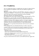
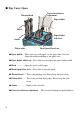
Name of Parts ■Front View Top cover Paper check window Operation switch Front cover Power switch ■Top cover .................... Open this cover when you set the paper. ■ Power switch .............. Press this switch to turn ON/OFF the printer. ■ Paper check window ... To check the status of paper. ■ Front cover ................. Open this cover to refill or set DIP-SW. ■ Operation switch • POWER .... When you turn on the power, the green light lights up. Refer to “Starting/Power”. • ERROR .....
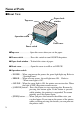
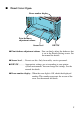
Back View Fanfold paper set in place I/F Cover Optional interface Connecter Power Connector ■Power Connector ... Connects AC adapter. ■Optional interface Connecter ... Connects computer. ■Fanfold Paper set in place ... Open this to use fanfold paper.To open the folder, remove the Top Cover and release. ■I/F Cover ... It removes by exchange of an I/F board.
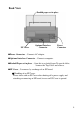
■ Top Cover Open Driver for darkness adjustment Thermal head Paper holder Head Paper holder slide lever Sensor Platen roller Head Open/Close lever ■ Paper holder ... When you use a roll paper, set the paper here. You can adjust the width according to the paper size. ■ Paper holder slide lever .. Press this lever to adjust the paper holder width. ■ Head ................ Open this part to refill paper. ■ Head Open/Close lever .. Press this to open the head. ■ Thermal head ....
■ Front Cover Open Error number display Print darkness adjustment volume Sensor level DIP-SW ■ Print darkness adjustment volume .. You can finely adjust the darkness that is set in the Printer Setting screen. See the manual for details. ■ Sensor level ...... Do not use this. Only for used by service personnel. ■ DIP-SW ............ Appropriate settings are set according to your printer system environment. You can change the settings. See the manual for details. ■ Error number display ..
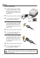
Power Cable Connection 1 2 3 Connect the power cable with the main unit and AC adapter as shown in the figure. When you insert the AC adapter in the main unit, set the stopper firmly. Plug in the power cable to the outlet. Use a Two-prong adapter if only a two-prong outlet is available. Stopper 1 2 Connect the power cable with the main unit and AC adapter as shown in the figure. When you insert the AC adapter in the main unit, set the stopper firmly. Plug in the power cable to the outlet.
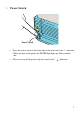
Power Switch Power Switch Press the power switch at the front side of the main unit in the “|” direction. * When you turn on the power, the POWER light lights up. Please confirm this. When you turn off the printer, flip the switch to the “ ” direction.
Computer Connection Connection example using Bi-directional parallel interface Use [Bi-directional parallel interface(sold separately)]. This printer operates by being connected to a computer. Turn off the power of the printer and connect to the computer with an interface cable connecting the bi-directional parallel interface connector at the rear panel of the printer. * If you are using a different optional interface board, refer to the instructions of its “Optional Interface”.
Paper Setting 1 2 Confirm the [PUSH] mark on the Left/Right side of the main unit. While depressing the mark on the cover, open the Top cover Press the Head Open/Close lever to the direction as shown in Figure. Confirm that the head is detached from the platen roller part, then lift the head in the direction as shown in the Figure. 3 While pressing the paper holder slide lever, adjust the paper holder to the paper size. 4 Set the paper on the paper holder.
5 Pull the paper,then pass under the sensor. 6 Close the head to the home position. 7 Depress the [PUSH] mark with finger until fixed firmly. Close the Top cover. 8 10 Set the top of the paper by pressing the [FEED] button. Finally, press the [ONLINE] button to change the online status.
Ribbon Setting Thermal Transfer model OKI POS T400/T410 only. 1 Confirm the [PUSH] mark on the Left/Right side of the main unit. While depressing the mark on the cover, open the Top cover. 2 Press the Head Open/Close lever to the direction as shown in Figure. Confirm that the head is detached from the platen roller part, then lift the head in the direction as shown in the Figure. 3 While pressing the Ribbon Core Lock button, pull the ribbon core from the unit. * The roller is also opened.
5 Please insert the ribbon core and fix firmly. * There are three depths according to the ribbon width. *Insert in the specified position by pressing the Lock button. 6 Pull out the ribbon along with the head. Stick the edge of the ribbon into the empty ribbon core by using a tape. Rotate the Ribbon Roll-up Knob in the clockwise direction and the wind up the ribbon several times. 7 Close the roller to the home position. Close the head to the home position.
Does not print correctly Print error • Paper set correctly? ➞ Please set the paper correctly. • Platen roller clean? ➞ If the platen roller is not clean, clean it using the Cleaning Kit (refer to the manual). • Paper replenished regularly? ➞ If the edge of the paper does not set regularly, the paper cannot be fed to the printer correctly. Please be sure to use paper. • Is the data or signal from the computer is correct? ➞ Please turn off and on the power of the printer.
• Paper set correctly? ➞ Please confirm that the paper is set correctly. • Platen roller clean? ➞ If the platen roller is not clean, clean the platen roller using the Cleaning Kit (refer to the manual). • Thermal head clean? No label is adhered to the head? ➞ If the thermal head is not clean, clean the head using the Cleaning Kit. ➞ If a label is adhered to the thermal head, remove the label. Please make sure not to remove the label using metal instruments such as a screw driver.
Failure? Please confirm the following before you decide it’s a mechanical failure. POWER light is not ON even if you turn on the machine. AC adapter and power cable are plugged in the outlet correctly? ➞ Plug in AC adapter and power cable into the outlet correctly. AC adapter is plugged in to the main unit correctly? ➞ Plug in the AC adapter to the main unit power connector firmly. No damages of the power cable? ➞ Replace the power cable. A new power cable is available in your local dealer.
AVERTISSEMENT DE LA FCC Les changements ou modifications qui ne sont expressément approuvés par la partie responsable d’assurer la conformité pourraient résilier votre droit d’utiliser l’équipement. Ce dispositif est conforme à la partie 15 de la réglementation FCC.
Contenu Noms des pièces .............................. 2 Alimentation..................................... 6 Connexion ordinateur....................... 8 Réglage papier.................................. 9 Réglage du ruban............................ 11 Impression incorrecte .................... 13 Témoin d’erreur allumé ................. 14 Panne? . ..........................................
Noms des pièces ■Vue avant Couvercle supérieur Fenêtre de vérification papier Commutateur de fonctionnement Couvercle avant Commutateur d’alimentation ■ Couvercle supérieur ........ Ouvrez ce couvercle quand vous réglez le papier. ■ Commutateur d’alimentation ......... Appuyez sur ce commutateur pour allumer et éteindre l'imprimante. ■ Fenêtre de vérification papier ....... Pour vérifier l’état du papier. ■ Couvercle avant Ouvrez ce couvercle pour remplir ou régler DIP-SW.
Vue arrière Papier en accordéon installé en place Couvercle I/F Connecteur d’interface optionnel Connecteur d’alimentation ■ Connecteur d’alimentation ........ Connecte l’adaptateur CA. ■ Connecteur d’interface optionnel........... Connecte l’ordinateur. ■ Papier en accordéon installé en place..... Ouvrez pour utiliser du papier en accordéon. Pour ouvrir la plieuse, retirez le couvercle supérieur et relâchez. ■ Couvercle I/F Vous pouvez le retirer pour installer une carte I/F.
■ Ouverture du couvercle supérieur Tête thermique Circuit de réglage d'assombrissement Support de papier Tête Levier de coulissement de support de papier Capteur Rouleau de platine de tête Levier d’ouverture/de fermeture ■ Support de papier ....... Quand vous utilisez du papier en rouleau, réglez le papier ici. Vous pouvez régler la largeur selon le format papier. ■ Levier de coulissement de support de papier ...... Appuyez sur ce levier pour ajuster la largeur du support de papier. ■ Tête......
■ Ouverture du couvercle avant Affichage du numéro d’erreur Degré de réglage de densité d’impression Niveau du capteur DIP-SW ■ Volume de réglage de densité d’impression....... Vous pouvez régler avec précision la densité paramétrée dans l‘écran Printer Setting. Voyez le manuel pour les détails. ■ Niveau de capteur ....... À ne pas utiliser. Usage réservé uniquement au personnel du service. ■ DIP-SW.......... Réglages appropriés paramétrés votre environnement de système d’impression.
Alimentation Connexion du câble 1 2 3 1 2 3 1 2 3 Branchez le câble d’alimentation dans l’unité principale et l’adaptateur CA comme montré dans la figure. Quand vous insérez l’adaptateur CA dans l’unité principale, réglez la butée fermement. Branchez le câble d’alimentation dans la prise murale. Utilisez un adaptateur à deux fiches si une prise de courant à deux trous est disponible. Connecter le câble d'alimentation avec l'unité principale et l'adaptateur CS tel que montré dans la figure.
- Commutateur d’alimentation Commutateur d’alimentation - Appuyez sur le commutateur d’alimentation à l’avant de l’unité principale dans la direction “|”.* Quand vous mettez sous tension l’unité, le témoin POWER s’allume. Veuillez le confirmer. - Quand vous éteignez l’imprimante, basculez le commutateur à la position “ ”.
Connexion à l’ordinateur L’exemple de connexion illustre une interface parallèle bidirectionnelle Utilisez une [interface parallèle bidirectionnelle (vendue séparément)]. Pour fonctionner, l’imprimante doit être raccordée à un ordinateur. Mettez hors tension l’imprimante et connectez-la à un ordinateur à l’aide d’un câble d’interface raccordant le connecteur d’interface parallèle bidirectionnelle au panneau arrière de l’imprimante.
Réglage papier 1 Confirmer la marque [PUSH] sur le côté gauche/droit de l’unité principale. Tout en enfonçant la marque, ouvrez le couvercle supérieur 2 Appuyez sur le levier d’ouverture/de fermeture de la tête dans la direction indiquée dans la figure. Confirmer que la tête est détachée du galet de platine, puis lever la tête dans la direction indiquée dans la figure. 3 Tout en appuyant sur le levier de coulissement du support de papier, réglez le support de papier selon le format de papier.
5 Tirez le papier, puis faites-le passer sous le capteur. 6 Fermez la tête à la position repos. 7 Enfoncez la marque [PUSH] avec le doit jusqu’à ce que le papier soit bien en place. Fermez le couvercle supérieur. 8 Réglez le haut du papier en appuyant sur la touche [FEED]. Finalement, appuyez sur le bouton [ONLINE] pour changer l’état en ligne.
Réglage du ruban Modèle à transfert thermique OKI POS T400/T410 seulement. 1 Confirmer la marque [PUSH] sur le côté gauche/droit de l’unité principale. Tout en enfonçant la marque, ouvrez le couvercle supérieur 2 Appuyez sur le levier d’ouverture/de fermeture de la tête dans la direction indiquée dans la figure. Confirmez que la tête est détachée du galet de platine, puis levez la tête dans la direction indiquée dans la figure.
5 Insérez le corps de ruban et installez fermement. * Il y a trois profondeurs selon la largeur du ruban. *Insérez dans la position spécifiée en appuyant sur le bouton de verrouillage. 6 Sortez le ruban avec la tête. Collez avec du ruban adhésif le bord du ruban dans le corps de ruban vide. Tournez la molette de rembobinage de ruban dans le sens horaire et rembobinez plusieurs fois le ruban. 7 Fermez le rouleau à la position repos. Fermez la tête à la position repos.
N’imprime pas correctement -- Erreur d’impression • • • • • • • Papier installé correctement? Installez le papier correctement. Galet de platine propre? Si le galet de platine n’est pas propre, nettoyez-le avec une trousse de nettoyage (voir le manuel). Papier réapprovisionné régulièrement? Si le bord du papier n’est pas réglé correctement, le papier ne peut être alimenté correctement dans l’imprimante. Utilisez du papier régulièrement.
• Papier installé correctement? Confirmez que le papier est réglé correctement. • Galet de platine propre? Si le galet de platine n’est pas propre, nettoyez avec le galet de platine avec une trousse de nettoyage (voir le manuel). • Tête thermique propre? Étiquette collée à la tête? Si la tête thermique n’est pas propre, nettoyez la tête avec une trousse de nettoyage. Si une étiquette est collée à la tête thermique, retirez l’étiquette.
Échec? Veuillez confirmer ce qui suit avant de décider si c’est une panne mécanique. - Le témoin d’alimentation n’est pas allumé même si vous allumez l’appareil. L’adaptateur CA et le câble d’alimentation sont branchés correctement dans la prise? Branchez l’adaptateur CA et le câble d'alimentation correctement dans la prise. L’adaptateur CA est branché correctement dans l’unité principale? Branchez l’adaptateur CA fermement dans le connecteur d’alimentation de l’unité principale.
16