
Fifty Six manual


Page 10 www.oldschoolmodels.com Construction Manual
cut the bottom strip first. It will start just at the outline you made,
rearwards and stop right at the start of TW1 (refer to the plans
for these locations). The top strip starts at the drawn outline, and
stops at where STS starts. Cut these for both sides, the glue them
in place - again making sure they are aligned with the bottom of
the cutouts - not the fuselage edges themselves. Also make sure
you have a left and right side - NOT two lefts or two rights. Again,
refer to the photo.
nStep 64 - Fuse Assembly (STS)
Locate both STS from BP10.
These stab supports are glued
in place on the inside of the
fuselage sides to “beef-up”
those areas. Pay attention to
the orientation and make sure
that the curved edges of the
STS pieces are matched up to
the cutouts in the fuselage sides.
nStep 65 - Fuse Assembly (BS, F6, F7, F8)
Locate BS from BP8, F6 from
BP7, and F7, F8 from BP5. Glue
the three formers into the BS
sheet, making sure they are
completely inserted into BS and
are each 90° in relation to BS.
Note that the tabs will extend
slightly from the bottom side of
BS and that is intentional. Once
you have these three formers in place, sand away the bit of the
tabs to give you a smooth bottom surface that should not need
any filler later on.
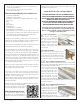
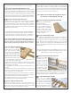
nStep 66 - Fuse Assembly (starboard fuse sheeting)
Locate the starboard side
sheeting you prepped
a few steps back. This
is now glued to the BS
and formers as shown
here. Make sure that the
notches in the formers are
fully inserted into the side
sheeting, and all of tabs in BS are fully inserted into the notches
along the bottom edge of the side sheeting. There’s a bit of a
gentle curve in this sheeting, so make sure that the side sheeting
follows that curve as you work. Also the tabs will extend past the
sheeting a little, so they can be smoothly sanded flush later on.
nStep 67 - Fuse Assembly (port side sheeting)
Locate the port side
sheeting and attach it
using the same techniques
you used in the previous
step.
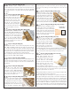
nStep 68 - Fuse Assembly (attach plywood box)
Now it’s time to test fit the plywood box to the back of the fuselage.
On the bottom of F5 is a notch. This notch is the key to lining up
these two pieces, as it should
be inserted into the cutout at
the front of BS. Dry fit this first,
and once the tab is in place, you
can then “rotate” the plywood
box as needed so it lines up
with the front of the fuselage
sides. Once you’re satisfied how these pieces go together, then
remove the plywood box and it’s time to glue it in place. If you’re
using CA for this step, use slower curing viscosities as you might
need a bit more working time to properly align the pieces. This is
one step where you might
want to use a different
glue - aliphatic resin and/or
carpenter’s could give you
a LOT more working time.
Epoxy could be used, but it
will add a bit of weight with
the amount of surface area
to cover on the side of the
fuselage box.
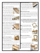
nStep 69 - Fuse Assembly (pushrods)
Before installing the top sheeting, now
might be a good time to think about
installing the elevator and rudder pushrods.
We typically use Dubro's Laser flexible
pushrods and you’ll see the outer red
tubing installed in this photo. We’ve pre-cut
pushrod guides into each of the formers, as
well as pre-cut pushrods exits on the rear of
the fuselage sides. If you use Dubro's, or a
similar type of pushrod system, don’t forget
to glue these tubes in place so they won’t move.
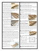
nStep 70 - Fuse Assembly (TS)
Locate TS from BP5. This is the top
sheeting and should be dry-fitted
first. There’s a notch cut into the
front edge that fits around the top
tab in F6. Then the TS’s side tabs
should be inserted into each of the
notches along the fuselage sides. When satisfied how it all goes
together, remove it, apply glue, and attach it in place.
nStep 71 - Fuse Assembly (sand the tail surfaces)
It’s time to attach the tail surfaces, but before you do, take the time
to sand the leading edges of the stab and vertical fin as they’ll be
much easier to do now, than after installation. Make sure that the
leading edges are nicely rounded, and you might want to test fit
them to the rear of the stab a few times as you sand, to get an idea
of where you might need a bit more shaping. However, do NOT
sand off the front notch that extends from the front of the vertical
fin. This is used to align this assembly to the fuselage.
nStep 72 - Fuse Assembly (attach the tail surfaces)
Once sanded, it’s time to trial fit the tail surfaces to the fuselage. With
the fuselage sitting upright and flat on your building board, you can then
slip the tail surface assembly in place, making sure that the front notch
is inserted into the cutout in F8, and the VF3 portion of the vertical fin is
nestled in between the fuselage sides. Now, if you take a measurement