
Fifty Six manual


Construction Manual www.oldschoolmodels.com Page 7
ledges just behind the front spar and ahead of the rear spar. Glue
these, centered across the two R5 ribs as shown on the plans.
n n Step 35 - Wing Assembly (aileron box - SH)
Locate one SH from LP5. This should now fit in the area between the
SH1’s you just installed. If not, lightly sand as necessary to obtain a
good fit. Note that there are 4 holes precut into the corners. With
a 1/16" bit, use SH as a guide to drill the 4 holes that will be used
to attach SH to the wing using 4 of the supplied 2-56 self-tapping
screws. Temporarily attach the hatch in place using these screws.
n n Step 36 - Wing Assembly (aileron box)
Now locate some of the scrap 1/4” square balsa stock trimmed
away from the trailing edge pieces. Cut two lengths that will run
between the front and rear spars. Glue these in position as shown
on the plans - flush with the top surface of SH1, and against the
1/4” square basswood mounts. Do NOT glue them to the SH hatch
as that needs to be removable.
Set the port wing half aside and begin work on the starboard
wing half. Tape the starboard wing plan and fresh wax paper
on your board. Then follow steps 1 through 36 to complete the
starboard wing half. Once finished, then move on to step 37.
Note that when building the port half that many of the parts
will need to be glued to the opposite side (the WH1, WH2, and
the wing stip pieces for instance). Always refer to the plans to
make sure you’re gluing the parts together in the correct way.
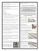
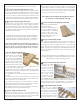
n Step 37 - Wing Assembly (D1, D2)
Locate D1 from LP1 and D2
from LP2. These are the dihedral
braces. Test fit these by sliding
them into both of the wing halves,
as shown. They should smoothly
push into the gap in the R1, R2
and R3 ribs until each brace is half
way inserted. Also make sure that
you insert them both in the same orientation - so they both point
“up” when the wing is held up-right.
Carefully sand as necessary so they both slide in as they should,
and allow the root (R1) ribs on both halves to fit flat against each
other, along their entire length.
Once satisfied with the fit, take the wing halves apart and remove
D1 and D2.
Now it’s time to mix up some epoxy and use it to coat the areas
where the D1 and D2 pieces will contact the spars and ribs. Also
coat the entire face of one of the R1 ribs.
When coated, slide all these pieces back together to form the
completed wing assembly. Hold these together with some tape
and/or clamps until the epoxy has cured completely.
While waiting for the glue to cure, wipe away any excess with a
paper-towel soaked in a bit of denatured alcohol.
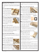
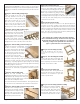
n Step 38 - Wing Assembly (ailerons)
Locate the two lengths of 5/16” x 1-1/4” tapered balsa sticks.
These are used as the ailerons. Refer to the plan for the correct
length, then cut one aileron from each piece. Also note the slight
angle on the aileron tips and cut/sand that in as well.
Note - if you prefer to make your Fifty Six a 3-channel system
(without ailerons), you can glue these strips to the trailing edge
of each wing to continue on the airfoil shape of the wing. We’ve
not done this with any of the prototypes as we prefer ailerons, but
there could be a couple of you out there that are aileron-phobic,
so here’s your chance to go really “old-school”.
This completes the assembly of the wing. Now it’s time for
the tail surfaces, starting with the vertical fin.
nStep 39 - Vertical Fin Assembly (VF1, VF2, VF4)
Locate VF1 and VF4 from BP12,
and VF2 from BP11.
Glue VF1 to VF2, making sure it
is properly aligned and that all
the tabs in VF1 are completely
seated in VF2’s tabs. Then,
glue VF4 to the top of the VF1/
VF2 assembly, making sure it is
properly oriented.
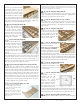
nStep 40 - Stab Assembly (S1 ribs)
Locate both S1 ribs from BP16. These are glued to the bottom of
the vertical fin assembly from the previous step, one on each side.
Using the pre-cut holes as a guide, glue one S1 to the vertical fin
piece, then flip it over and glue the other S1 to the other side.
Make sure these are properly aligned, and straight with each other.
Refer to the drawing of this section shown on the side view of the
fuselage plans.
Remove the wing plans from your building surface, then cutout
and attach the plans for the horizontal stab and elevator. Cover it
with wax paper and tape everything into place.
nStep 41 - Stab Assembly (SP5, S2-S7 ribs)
Locate SP5 from BP2,
and both sets of S2-
S7 ribs from BP16.
Slide the vertical fin
assembly on to SP5, all
the way to the middle.
Then, slide one S2
on each side of SP5,
noting the orientation
(all underside tabs pointing the same way, and the leading edges
also oriented correctly. Continue on with both S3s, S4s, S5s, S6s,
and finally S7s. Place this “assembly down on to the plans and
begin to carefully slide the stab ribs into their proper position.
nStep 42 - Stab Assembly (stab ribs)
Using the 90° alignment
triangle, it’s time to start gluing
the stab ribs to SP5. Start with
the vertical fin, with it perfectly
centered, 90° to the buliding
surface and straight. Then work
your way through one side of