
Fifty Six manual


Construction Manual www.oldschoolmodels.com Page 9
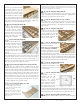
nStep 59 - Fuse Assembly (SS)
Locate both SS from LP3. These
are the inner supports for the
wing saddle. One is glued in
place on the inside of FSP and
FSS as shown here. Make sure
their edges area aligned with
the fuselage sides and they are
properly oriented.
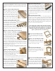
nStep 60 - Fuse Assembly (nose gear block)
This might seem like a strange time to do this,
but it’s actually the perfect time. Inside the
hardware bag is a smaller bag which has all the
components needed to make the nose gear
assembly. In this group of parts is the nylon
nose block, the 4 mounting screws, and the 4
t-nuts.
Using the etched lines on F1, you can easily
locate this nose-block so it’s straight, as the
lines should appear inside each of the 4 block’s four mounting holes. Using
a 3/32” bit, drill these four mounting positions into F1.
Then use the 4 screws and t-nuts to fasten this in position. You might want
to use a bit a thread lock and cut away the extra length from interfering
with the tank and/or battery installation later on.
nStep 61 - Fuse Assembly (SS1, SS2, SS3)
Locate both SS2s and SS3s
from BP6, as well as both
SS1s from BP7. Glue one
SS1 to one SS2, making
sure that all the tabs on
SS2 are completely seated
into the notches cut into
SS1. Also make sure that
the pieces are flat along
this entire joint. Then glue
SS3 to the end of this assembly using the same technique.
Make 2 assemblies.
nStep 62 - Fuse Assembly (fuse side prep)
Take the plywood fuselage box
and test fit one of the balsa
fuselage sides to the port side.
Align it so the dowel holes and
edges match. Now, using a
pencil, trace an outline of the end
of the fuselage box on the inside
face of the balsa side.
Remove that side, then do the same for the starboard side, again
tracing the end on the inside face of the balsa sheeting.
nStep 63 - Fuse Assembly (fuse side prep)
Locate two 3/16” square balsa strips. These are used to create
interior ledges on the
top and bottom of the
fuselage sides. The
strips will be positioned
along the bottom of the
cutouts on the fuselage
sides (refer to the
photo). Measure and
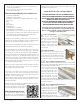
nStep 54 - Fuse Assembly (F1/F2)
Locate F1 from LP2 and F2 from LP4. These are
glued together as shown to form the firewall.
Make sure F1 is aligned with F2 and that the
etched nose-gear alignment lines are visible.
We recommend epoxy for this step.
nStep 55 - Fuse Assembly (TR1)
Locate TR1 from LP2. Note that TR1
has a small circle engraved on the
top surface - this designates the
starboard side of the fuselage. Both
tabs on the front of TR1 should be
inserted into the pre-cut holes in F2
as shown here. Also note that this
piece is NOT glued perpendicular
to TR1. Instead, use the DH-JIG
guide you used during the wing
construction to give the needed downthrust angle that will become
apparent in the next few steps.
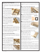
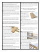
nStep 56 - Fuse Assembly (FSS)
Locate FSS from LP5. This
is the starboard side of the
fuselage and should be
attached to the plywood
TR2 assembly you’ve just
created over the last few
steps. Take the time to dry-
fit this first, to get an idea
of how all the tabs fit into FSS’s precut holes. When you’re ready,
glue FSS in place. Make sure that all of the tabs are fully seated
into each of the holes, and that FSS follows the gentle curvature
cut into TR2.
nStep 57 - Fuse Assembly (FSP)
Locate FSP from LP4.
This is the port side
of the fuselage and
should be attached
to the port side of
the plywood box.
Again, take the time
to dry-fit this first, to
get an idea of how all
the tabs fit into FSP’s
precut holes. When you’re ready, glue FSP in place. Make sure that
all of the tabs are fully seated into each of the holes, and that FSP
follows the gentle curvature cut into TR2.
nStep 58 - Fuse Assembly (TR1)
Now the TR1 assembly is glued in place, between the fuselage
sides and into F3A. To do this carefully bend the fuselage sides
apart a bit, allowing the assembly to slide into place. When
properly aligned, all of the tabs should pop into the pre-cut holes
on both FSP and FSS.
When satisfied with this dry-fit, remove the tray, apply glue, and
put in back in position. Make sure it’s held in place and that the
fuselage sides continue their gentle curvature.