Bookcase Installation Guide TOOLS REQUIRED: Powered screwdriver myolgoffice.
BOOKCASE Installation Guide PARTS PAG
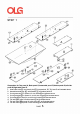
BOOKCASE Installation Guide * To prevent possible scratches or damage, assemble the bookcase on a soft surface such as a blanket, carpet or packaging. STEP 1: Recommended 2-person Step Insert cam bolt (c1) and dowel pins (d1) into panels A, D, G, X and Z as illustrated above, and assemble metal legs (m2) with screws (s1) on bottom panel G. STEP 2: Insert cam bolts (c1) and dowel pins (d1) on panel X and Z into cams on panel D and tighten in a clockwise direction as illustrated above.
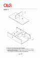
BOOKCASE Installation Guide STEP 3: Insert cam bolts (c1) and dowel pins (d1) on panel G and A into cams on panel X, Z and D, then cover the cam covers (c2) on the top of cams. STEP 4: Insert threaded dowel pins (p1) into panels X and Z, then put the four panels E on the top of threaded dowel pins (p1) as illustrated above.
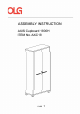
ASSEMBLY INSTRUCTION AXIS Cupboard 1800H ITEM No.
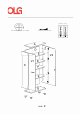
Incorrect r( The arrow direction=front The turning direction of attaching V2 V1 • PAGE 2 Correct
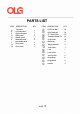
PARTS LIST ITEM DESCRIPTION QTY. ITEM DESCRIPTION QTY.
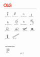
i 6*35 Cam Bal t-25 © I � 8*30 Dowel Pin-24 (e} Threaded Dowel Pin-15 @ (@ Lock Catch-1 @ @ 4*22 Fix Bolt-4 @ Handle-2 Metal Leg-4 @ H (% ) Cam Cover-25 @ Height Adjuster- 4 0 Lock Catch-1 Pre-installed parts @cam PAGE 4 Hinge Body-8 0 4*16 Screw-50 0 © Lock-1 Hinge Stand-8
STEP 1 · · · . . � . .r . Preparation for Top panel A, Back panel D,lmmovable panel F,Bottom panel G,Left side panel X,Right side panel Z. 1, Insert cam bolts@) and dowel pins@ into panels A ,D,F,G,X and Z as illustrated above. 2, Assemble metal legs @ with screws§ on bottom panel G. 3, Fix hinge stands@ to panels X,Z with screws@)as illustrated above. 4, Fix hinge bodies(93 to panels V1 and V2 with screws@as illustrated above. 5, Fix handles� to panels V1 and V2 with fix bolts@as illustrated above.
STEP 2 D Left side panel X and Right side panel Z assembly. 1 , Fix cams on panel F into cam bolts@ on panel D and tighten in a clockwise direction as illustrated above. 2, Insert cam bolts c1 and dowel pins@ on panel X and Z into cams on panel D ,F and tighten in a clockwise direction as illustrated above.
STEP 3 Bottom panel G and Top panel A assembly. 1, Insert cam bolts@) and dowel pins@]) on panel G and A into cams on panel X,Z and D and tighten in a clockwise direction as illustrated above. 2, Cover the cam covers@ on the top of cams. STEP 4 Moveable shelf E assembly. 1, Insert threaded dowel pins@) into panels X ,D and Z as illustrated above. 2, Put the three panels E on the top of threaded dowel pins @) as illustrated above.
STEP 5 14 B � 1: LOOSEN ® SCREWS 2: ADJUST D'O'OR VERTICAL 3: TIGHTEN @ SCREWS AGAIN r ������ �PTH 3: TIGHTEN SCREW €)AGAIN Door panel V1 ,V2 assembly.
You have now successfully completed the assembly on item: AXIS Cupboard 1800H ITEM No.:AXC18 Remove all QC and panel labels and wipe clean using a damp cloth and general household cleaner .
ASSEMBLY INSTRUCTION AXIS Caddy Bookcase 993W ITEM No.
Incorrect The turning direction of attaching ...
PARTS LIST ITEM DESCRIPTION QTY. ITEM DESCRIPTION QTY.
STEP 1 Preparation for Top panel A, Back panel D,Bottom panel G,Left side panel X, Vertical panel Y,Right side panel Z . 1, Insert cam bolts{§} and dowel pins@ into panels A ,D,G,X,Y and Z as illustrated above. 2, Assemble castor@with screws @ on bottom panel G.
STEP 2 Cams/holes on the panel Y to face to panel X. Back panel D, Left side panel X ,Right side panel Z,Vertical panel Y assembly. 1... Fix cams on panel X,,Z, into cam bolts@) on panel D and tighten in a clockwise direction as illustrated above. STEP 3 D Bottom panel G and Top panel A assembly. 1... Insert cam bolts@ and dowel pins@ on panel G and A into cams on panel X,Y,Z and D and tighten in a clockwise direction as illustrated above. 2... Cover the cam covers@ on the top of cams.
STEP 4 Moveable shelf E assembly. 1 � Insert threaded dowel pins (e}) into panels X,D,Y and Z as illustrated above. 2� Put the TWO panels Eon the top of threaded dowel pins@ as illustrated above.
You have now successfully completed the assembly on item: AXIS Caddy Bookcase 993W ITEM No.:AXCMB Remove all QC and panel labels and wipe clean using a damp cloth and general household cleaner.
ASSEMBLY INSTRUCTION AXIS System Tambour Insert-Studio ITEM No.
11ie turning direction of attaching ..
PARTS LIST ITEM DESCRIPTION QTY. ITEM A X1 Top panel Left side panel Right side panel Back panel Bottom panel Moveable shelf 1 1 1 1 1 1 @ @) @ @) ®) z D G i @ 6"35 Cam Bolt-16 QTY.
STEP 1 P19paratlon for Top panel A, Back panel D,Bottom panel G,Leftalde panel X1, Right aide panel Z . 1, Insert cam bolts@ and dowel pins @ into panels A .D.G,X1 and Z as illustrated above.
STEP 2 Left aide panel X1 and Right aide panel Z aaaembly. 1.. Insert cam bolts@ and dowel pins 41).>n panel X1 and Z Into cams on panel D and tighten i'l a clockwise direction as Illustrated above. STEP 3 D Note: All the roller doors must place into the groove of the top panel A. Bottom panel G and Top panel A assembly. 1.. Insert cam bolts @ and dowel pi"ls (!)>n panel G and A into cams on panel X.Z and D and tighten in a clockwise di'ection as illustrated above. 2..
STEP 5 Moveable shelf E assembly. 1, Insert threaded dowel pils � into panels X and Z as illustrated above. 2, Put the two panels Eon the top of threaded dowel pins �s illustrated above.
ASSEMBLY INSTRUCTION AXIS Credenza 1800W ITEM No.
Incorrect ...
PARTS LIST ITEM DESCRIPTION QTY. ITEM DESCRIPTION QTY.
i 0 6*35 Cam Bal t-24 (e} Threaded Dowel Pin-10 0 0 Lock Catch-2 � @ Hinge Stand-8 © I 8*30 Dowel Pin-24 @ Metal Leg-6 H @ (% ) Cam Cover-24 Lock Catch-2 � @ Big curve Hinge & Mount Plate-4 (V1 and V4) t 0 4*16 Screw-62 0 @ Height Adjuster- 6 T � @ i � @ 4*22 Fix Bolt-8 Lock-2 � Handle-4 � @ Small curve Hinge & Mount Plate-4 (V2 and V3) ' IMPORTANT: Please note the difference between parts g2 and g3.
STEP 1 IMPORTANT: Please note the difference between parts 13 and 14. Each hinge is specifically designed for their unique position. Correct installation is essential for a successful assembly of this credenza. Preparation for Top panel A,Bottom panel G,Left side panel X,Right side panel Z,Vertical panel Y,Door panel V1,V2,V3 and V4. 1, 2, 3, 4, 5, 6, Insert cams bolts@ and dowel pins@ into panels A,G,X,and Z as illustrated above. Fix hinge stands@ to panels X,Z and Y with screws@as illustrated above.
STEP 2 Cams/holes on the panel Y to face to panel X. Top panel A, Back panel D, Left side panel X ,Right side panel Z,Vertical panel Yassembly. 1, Fix cams on panel X,Z,Y,D into cam bolts@) on panel A and tighten in a clockwise direction as illustrated above.
STEP 3 Bottom panel G assembly. 1 � Fix cams on panel X,Y,Z and Dinto cam bolts@) on panel G and tighten in a clockwise direction as illustrated above. 3, Cover the cam covers @ on the top of all the cams. STEP 4 Moveable shelf E assembly. 1.lnsert threaded dowel pins (ey into panels X,Y,Z and Das illustrated above. 2.Put the two panels E on the top of threaded dowel pins @ as illustrated above.
STEP 5 V4 X V1 V3 V2 C ,, B � 1: LOOSEN ® SCREWS 2: ADJUST Dc:fOR VERTICAL 3: TIGHTEN @ SCREWS AGAIN r ��:f �� �PTH 3: TIGHTEN SCREW ®AGAIN Door panel V1,V2,V3,V4 assembly.
You have now successfully completed the assembly on item: AXIS Credenza 1800W ITEM No.
ASSEMBLY INSTRUCTION Axis Locker Single ITEM No.
Incorrect The turning direction of attaching r( The arrow direction=front z , ) V X , ) PAGE 2 V Correct
PARTS LIST ITEM DESCRIPTION QTY. ITEM DESCRIPTION QTY. A X Top panel Left side panel Right side panel Back panel Bottom panel Immovable panel Batten Door panel 1 1 1 1 1 2 1 3 @ @ @ 6*35 Cam Bolt 8*30 Dowel pin (%") Cam Cover 29 28 4*16 Screw 3.
i 6*35 Cam Bal t-29 i @ 3.
STEP 1 Preparation for Top panel A,Bottom panel G,Left side panel X,Right side panel Z,Door panel V 1, 2, 3, 4, Insert cams bolts@ and dowel pins@) into panels A,G,X,and Z as illustrated above. Fix hinge stands@ to panels X,Z with screws@as illustrated above. Fix hinge bodies� to panels V with screws@as illustrated above. Fix handles� to panels V with fix bolts@as illustrated above. 5, Fix lock@to panel V with screws@as illustrated above. 6, Fix lock catch Oto panel X with screws@ as illustrated above.
STEP 2 D Bottom panel G, Back panel Batten O assembly. 1 � Insert cam bolts€]) on panel G into cams on panel O and tighten in a clockwise direction as illustrated above. Left side panel X and Right side panel Z assembly. 1 � Insert cam bolts@ and dowel pins@ on panel X and Z into cams on panel D and tighten in a clockwise direction as illustrated above.
STEP 2 Z. X Top panel A assembly. 1, Insert cam bolts(§]) and dowel pins@ on panel A into cams on panel X,Z and D and tighten in a clockwise direction as illustrated above. 2, Cover the cam covers@ on the top of cams.
STEP 5 ' ) V X ' ) V C B ,, � B 1: LOOSEN ® SCREWS 2: ADJUST Dc:foR VERTICAL 3: TIGHTEN SCREWS AGAIN ® r ��:f �� �PTH 3: TIGHTEN SCREW ®AGAIN Door panel V1 ,V2 assembly.
ASSEMBLY INSTRUCTION Axis Locker Single ITEM No.
Incorrect The turning direction of attaching r( The arrow direction=front ' ) y ' X ) y ' ) y PAGE 2 Correct
PARTS LIST ITEM DESCRIPTION QTY. ITEM DESCRIPTION QTY. A X Top panel Left side panel Right side panel Vertical panel Back panel Bottom panel Immovable panel Immovable panel Batten Door panel 1 1 1 1 1 1 2 2 1 6 @ @ @ 6*35 Cam Bolt 8*30 Dowel pin (%") Cam Cover 48 46 4*16 Screw 3.
i 6*35 Cam Bal t-48 i @ 3.
STEP 1 Preparation for Top panel A,Bottom panel G,Left side panel X,Right side panel Z,Vertical panel Y,Door panel V . 1, 2, 3, 4, 5, 6, Insert cams bolts@ and dowel pins@) into panels A,G,X,and Z as illustrated above. Fix hinge stands@ to panels X,Z and Y with screws@as illustrated above. Fix hinge bodies� to panels V with screws@as illustrated above. Fix handles� to panels V with fix bolts@as illustrated above. Fix lock@to panel V with screws@as illustrated above.
STEP 2 ' ' D y ' ""· ' ' Bottom panel G , Back panel D and Batten O assembly. 1 � Insert cam bolts@) on panel G into cams on panel O and tighten in a clockwise direction as illustrated above. 2� Insert cam bolts@) on panel G into cams on panel D and tighten in a clockwise direction as illustrated above.
STEP 3 ' ' (),, ., D ' ' ., Back panel D, bottom panel G,Vertical panel and Batten 0 assembly. 1.lnsert cam bolts@) on panel X and Z into cams on panels D,G,O and tighten in a clockwise direction as illustrated above.
STEP 4 D Top panel A ,Back panel D, Left side panel X ,Right side panel Z,Vertical panel Y .bottom panel G,Vertical panel and Batten O assembly. 1, Insert cam bolts@on panel A into cams on panels D,X,Y,Z and tighten in a clockwise direction as illustrated above. 2, Cover the cam covers @ on the top of all the cams as illustrated above.
STEP 5 z ) ,v X ) V , , ) V C B ,, � B V 1: LOOSEN ® SCREWS 2: ADJUST Dc:foR VERTICAL 3: TIGHTEN SCREWS AGAIN ® r ��:f �� �PTH 3: TIGHTEN SCREW ®AGAIN Door panel V1 ,V2 assembly.
ASSEMBLY INSTRUCTION AXIS Planter for Tambour Cabinet 750W ITEM No.
Incorrect The turning direction of attaching ...
PARTS LIST ITEM DESCRIPTION QTY. ITEM DESCRIPTION QTY.
STEP 1 Preparation for Bottom panel G, side panel 0,01 1 � Insert cam bolts@) and dowel pins@ into panels G,O and 01 as illustrated above.
STEP 2 Bottom panel G, side panel O assembly. 1, Insert cam bolts@ and dowel pins@]) on panel O into cams on panel G and tighten in a clockwise direction as illustrated above. STEP 3 01 Side panel 0,01 assembly. 1, Insert cam bolts@ and dowel pins@ on panel 01 into cams on panel G and tighten in a clockwise direction as illustrated above. 2, Cover the cam covers@ on the top of cams.
STEP 4 6 PCS Transparant plastic sticker I PAGE 6
You have now successfully completed the assembly on item: AXIS Planter for Tambour Cabinet 750W ITEM No.:AXPBOX200 Remove all QC and panel labels and wipe clean using a damp cloth and general household cleaner.
ASSEMBLY INSTRUCTION AXIS Tambour Cabinet 1250H ITEM No.
Incorrect The turning direction of attaching ...
PARTS LIST ITEM DESCRIPTION QTY. ITEM DESCRIPTION QTY.
STEP 1 Preparation for Top panel A,bottom panel G,Vertical batten O,Left side panel X, X1,Right side panel Z, 21,back panel D. 1, Insert cams bolts@ and dowel pins@ into panels A,G,X,X1 ,Zand Z1 as illustrated above. 2, Insert dowel pins@into panels D,O as illustrated above.
STEP 2 D Back panel D, left side panel X,X1,right side panel Z,21 and Batten O assembly. 1-. Insert cam bolts@) on panel X,X1 and Z,Z1 into cams on panels D,O and tighten in a clockwise direction as illustrated above. STEP 3 D Top panel A assembly. 1-. Insert cam bolts@ on panel A into cams on panels X,X1 ,Z,Z1 ,D,O and tighten in a clockwise direction as illustrated above. 2-. Tighten the two cams of the panel X depend on the through hole in the panel X1 Z1 as illustrated above.
STEP 4 Note: sure the pillow components are at the bottom side. D z 12PCS Note: All the roller doors must place into the groove of the top panel A.
STEP 5 Bottom panel G assembly. 1, Insert cam bolts(§]) on panel G into cams on panels X,X1 ,D,Z,Z1 ,0 and tighten in a clockwise direction as illustrated above. 2, Tighten the panel bottom G on the panel X,Z with fix bolt @as illustrated above. 3, Fix Metal Leg@ to panels G with screws@as illustrated above. STEP 6 Moveable shelf E assembly. 1, Insert threaded dowel pins @ into panels D,X1 and Z1 as illustrated above. 2, Put the tow panels Eon the top of threaded dowel pins@as illustrated above.
You have now successfully completed the assembly on item: AXIS Tambour Cabinet 1250H ITEM No.
ASSEMBLY INSTRUCTION AXIS Tambour Cabinet 900H ITEM No.
Incorrect The turning direction of attaching ...
PARTS LIST ITEM DESCRIPTION QTY. ITEM DESCRIPTION QTY.
STEP 1 X1 ..···· Preparation for Top panel A,bottom panel G,Vertical batten O,Left side panel X, X1,Right side panel Z, 21,back panel D. 1, Insert cams bolts@ and dowel pins@ into panels A,G,X,X1 ,Zand Z1 as illustrated above. 2, Insert dowel pins@into panels D,O as illustrated above.
STEP 2 D Back panel D, left side panel X,X1,right side panel Z,21 and Batten O assembly. 1-. Insert cam bolts@) on panel X,X1 and Z,Z1 into cams on panels D,O and tighten in a clockwise direction as illustrated above. STEP 3 D D :zt X Top panel A assembly. 1-. Insert cam bolts@ on panel A into cams on panels X,X1 ,Z,Z1 ,D,O and tighten in a clockwise direction as illustrated above. 2-. Tighten the two cams of the panel X depend on the through hole in the panel X1 Z1 as illustrated above.
STEP 4 Note: sure the pillow components are at the bottom side. z 12PCS Note: All the roller doors must place into the groove of the top panel A.
STEP 5 Bottom panel G assembly. 1, Insert cam bolts(§]) on panel G into cams on panels X,X1 ,D,Z,Z1 ,0 and tighten in a clockwise direction as illustrated above. 2, Tighten the panel bottom G on the panel X,Z with fix bolt @as illustrated above. 3, Fix Metal Leg@ to panels G with screws@as illustrated above. STEP 6 X Moveable shelf E assembly. 1, Insert threaded dowel pins (e_p into panels D,X1 and Z1 as illustrated above. 2, Put the One panels Eon the top of threaded dowel pin@ as illustrated above.
You have now successfully completed the assembly on item: AXIS Tambour Cabinet 900H ITEM No.:AXT9 Remove all QC and panel labels and wipe clean using a damp cloth and general household cleaner.
ASSEMBLY INSTRUCTION AXIS Tambour Mobile ITEM No.
Incorrect The turning direction of attaching ...
PARTS LIST ITEM DESCRIPTION QTY. ITEM A Tambour Mobile 1 @ @ @) Castor-4 Castor 4*16 Screw i 0 4*16 Screw-16 PAGE DESCRIPTION 3 QTY.
STEP 1 Preparation for Tambour Mobile A 1 � Assemble castor@)with screws @on bottom panel G.
You have now successfully completed the assembly on item: AXIS Tambour Mobile ITEM No. :AXTM Remove all QC and panel labels and wipe clean using a damp cloth and general household cleaner.