MSP430-5510STK development board USER’S MANUAL Revision D, September 2013 Designed by OLIMEX Ltd, 2011 All boards produced by Olimex LTD are ROHS compliant
OLIMEX© 2013 MSP430-5510STK user's manual Disclaimer: © 2013 Olimex Ltd. Olimex®, logo and combinations thereof, are registered trademarks of Olimex Ltd. Other terms and product names may be trademarks of others. The information in this document is provided in connection with Olimex products. No license, express or implied or otherwise, to any intellectual property right is granted by this document or in connection with the sale of Olimex products.
OLIMEX© 2013 MSP430-5510STK user's manual Table of Contents CHAPTER 1: OVERVIEW........................................................................................5 1. Introduction to the chapter.......................................................................................................5 1.1 Features.....................................................................................................................................5 1.2 Organization...........................................
OLIMEX© 2013 MSP430-5510STK user's manual 8.1 Eagle schematic......................................................................................................................19 8.2 Physical dimensions...............................................................................................................21 CHAPTER 9: REVISION HISTORY.....................................................................22 9. Introduction to the chapter.............................................................
OLIMEX© 2013 MSP430-5510STK user's manual CHAPTER 1: OVERVIEW 1. Introduction to the chapter Thank you for choosing the MSP430-5510STK development board from Olimex! This document provides a User’s Guide for the Olimex MSP430-5510STK development board. As an overview, this chapter gives the scope of this document and lists the board’s features. The document’s organization is then detailed.
OLIMEX© 2013 – – – – MSP430-5510STK user's manual Chapter 6 covers the connector pinout, peripherals and jumper description Chapter 7 shows the processor diagram and memory map Chapter 8 provides the schematics Chapter 9 contains the revision history Page 6 of 24
OLIMEX© 2013 MSP430-5510STK user's manual CHAPTER 2: SETTING UP THE MSP430-5510STK BOARD 2. Introduction to the chapter This section helps you set up the MSP430-5510STK development board for the first time. Please consider first the electrostatic warning to avoid damaging the board, then discover the hardware and software required to operate the board. The procedure to power up the board is given, and a description of the default board behavior is detailed. 2.
OLIMEX© 2013 MSP430-5510STK user's manual -Plug mini USB with at least 5V to the board OR connect a charged 3.7V Li-Po battery to the respective connector OR -Set the jumpers P_IN closed, P_OUT open so you can power from JTAG connector On powering the board via USB the PWR LED, LED1 and the display should turn on. On powering the board via JTAG the LED1 and the display should turn on. The board has a Li-Po charger.
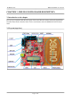
OLIMEX© 2013 MSP430-5510STK user's manual CHAPTER 3: MSP430-5510STK BOARD DESCRIPTION 3. Introduction to the chapter Here you get acquainted with the main parts of the board. Note the names used on the board differ from the names used to describe them. For the actual names check the MSP430-5510STK board itself. 3.
OLIMEX© 2013 MSP430-5510STK user's manual CHAPTER 4: THE MSP430F5510 MICROCONTROLLER 4. Introduction to the chapter In this chapter is located the information about the heart of MSP430-5510STK – its microcontroller. The information is a modified version of the datasheet provided by its manufacturers. 4.1 The microcontroller Main processors features: • Low Supply-Voltage Range, 1.8 V to 3.
OLIMEX© 2013 MSP430-5510STK user's manual CHAPTER 5 CONTROL CIRCUITY 5. Introduction to the chapter Here you can find information about reset circuit, power circuit and quartz crystal locations. 5.1 Reset MSP430-5510STK reset circuit includes R7 (33 KΩ), R8(330 Ω), MSP430F5510 pin 48 (RST/NMI/SBWTTDIO) and a RESET button. 5.2 Clocks Real time clock (RTC) Q1 is connected to pins 8 and 9 of the processor. 4 MHz quarz crystal Q2 is found at pins 45 and 46 of the processor.
OLIMEX© 2013 MSP430-5510STK user's manual CHAPTER 6: HARDWARE 6. Introduction to the chapter In this chapter are presented the connectors that can be found on the board all together with their pinout. Proto area is shown. Jumpers functions are described. Notes and info on specific peripherals are presented. Notes regarding the interfaces are given. 6.1 Battery connector The battery connector is used only to charge 3.7V Lithium batteries. It cannot be used to power the board.
OLIMEX© 2013 MSP430-5510STK user's manual 6.3 UEXT MSP430-5510STK board has UEXT connector and can interface Olimex's UEXT modules. For more information on UEXT please visit: https://www.olimex.com/Products/Modules/UEXT/ Pin # Signal name 1 +3.
OLIMEX© 2013 MSP430-5510STK user's manual 6.4 Pads on the proto area For your convenience the pads are named individually near each of them. Please take extra care about the numbering but consider that there might be offset. Pad name Signal 3.3V 3.3V row of pads 3.3VA 3.3VA row of pads +5V +5V 3.3V_E 3.
OLIMEX© 2013 MSP430-5510STK user's manual AGND Analog GND row of pads GND GND row of pads 6.5 USB mini connector Pin # Signal name 1 +5V 2 D- 3 D+ 4 Not connected 5 GND 6.6 SD/MMC slot Pin # Signal name 1 DAT2 2 DAT3/CS 3 CMD/DI 4 VDD 5 CLK/SCLK 6 VSS 7 DAT0/DO 8 DAT1 6.7 Jumper description P_OUT/P_IN This jumper controls power on pins 2 and 4 of the JTAG connector. When in P_OUT is closed 3.3V can be measured at pin 4. Check the schematic for more info.
OLIMEX© 2013 MSP430-5510STK user's manual 3.3V_JP If open open stops processor and proto area pads powering. Default state is closed. SW_SCL/HW_SCL; SW_SDA/HW_SDA These two jumpers control whether the SCL and SDA signals to be implemented on software or hardware level. When in position SW_SCL/SW_SDA software implementation. Default position is SW_SCL; SW_SDA. CHG_D If closed stops the battery charger. Default state is open. AGND_E Analog GND is disabled if open. If closed Analog GND is enabled.
OLIMEX© 2013 MSP430-5510STK user's manual 6.9 Additional hardware components The components below are mounted on MSP430-5510STK but are not discussed above.
OLIMEX© 2013 MSP430-5510STK user's manual CHAPTER 7: MEMORY AND BLOCK DIAGRAM 7. Introduction to the chapter Below is located the block diagram of the processor and on the next page you can find a memory map for this family of processors. It is strongly recommended to refer to the original datasheet released by Texas Instruments for ones of higher quality. 7.
OLIMEX© 2013 MSP430-5510STK user's manual CHAPTER 8: SCHEMATICS 8. Introduction to the chapter In this chapter are located the schematics describing logically and physically MSP430-5510STK. 8.1 Eagle schematic MSP430-5510STK schematic is visible for reference here. You can also find them on the web page for MSP430-5510STK at our site: https://www.olimex.com/Products/MSP430/Starter/MSP4305510STK/. They are located in HARDWARE section. The EAGLE schematic is situated on the next page for quicker reference.
OLIMEX© 2012 MSP430-5510STK user's manual RESET CIRCUIT POWER_SUPPLY 3.3V 3.3V_E R4 0R(NA) 0R MCP17 00T -33 02E/MB FET1 IRLM L6 402 1 M CP 738 12T -42 0I/OT 100nF 1 2 AGND_E BH14S R15 GND C9 100nF 100nF C11 12 27 2 20nF/25V 470nF/16V 13 43 VCORE V18 10 44 100nF P1_7/TA1_0 P1_6/TA1CLK/CBOUT P1_5/TA0_4 P1_4/TA0_3 P1_3/TA0_2 P1_2/TA0_1 P1_1/TA0_0 P1_0/TA0CLK/ACLK DVSS1 DVSS2 7 C14 10uF/6.
OLIMEX© 2013 MSP430-5510STK user's manual 8.2 Physical dimensions Note that all dimensions are in inches.
OLIMEX© 2013 MSP430-5510STK user's manual CHAPTER 9: REVISION HISTORY 9. Introduction to the chapter In this chapter you will find the current and the previous version of the document you are reading. Also the web-page for your device is listed. Be sure to check it after a purchase for the latest available updates and examples. 9.
OLIMEX© 2013 MSP430-5510STK user's manual 9.2 Web page of your device The web page you can visit for more info on your device is https://www.olimex.com/Products/MSP430/Starter/MSP430-5510STK/. There you can find more info and some examples.
OLIMEX© 2013 MSP430-5510STK user's manual 9.3 Product support For product support, hardware information and error reports mail to: support@olimex.com. All document or hardware feedback is welcome. Note that we are primarily a hardware company and our software support is limited. Please consider reading the paragraph below about the warranty of Olimex products. All goods are checked before they are sent out.