
User manual


OLIMEX© 2013 MSP430-5510STK user's manual
CHAPTER 1: OVERVIEW
1. Introduction to the chapter
Thank you for choosing the MSP430-5510STK development board from Olimex! This document
provides a User’s Guide for the Olimex MSP430-5510STK development board. As an overview,
this chapter gives the scope of this document and lists the board’s features. The document’s
organization is then detailed.
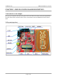
The MSP430-5510STK development board enables code development of applications running on
the MSP430F5510 microcontroller, manufactured by Texas Instruments.
1.1 Features
• MCU MSP430F5510 with 32K Bytes Program Flash, 4K Bytes RAM, 25Mhz LCD display
8 alphanumeric
• micro SD card connector
• Li-Po battery on-board charger
• USB connector, and USB bootloader support
• two buttons
• 2 status LEDs
• access to every pin near prototype area
• Reset button
• UEXT connector that allows other Olimex's modules (MOD-MP3, MOD-NRF24L01, etc.)
to be connected
• JTAG connector
• JTAG Power_In and Power_Out jumpers
• 32 768 Hz oscillator crystal
• 4 Mhz crystall oscillator
• Power supply voltage regulators and filtering capacitor
• Power on Led
• PCB: FR-4, 1.5 mm (0,062"), soldermask, white silkscreen component print
• Dimensions: 100x 80mm (3.94x 3.14")
1.2 Organization
Each section in this document covers a separate topic, organized as follow:
– Chapter 1 is an overview of the board usage and features
– Chapter 2 provides a guide for quickly setting up the board
– Chapter 3 contains the general board diagram and layout
– Chapter 4 describes the component that is the heart of the board: the MSP430F5510
microcontroller
– Chapter 5 is an explanation of the control circuitry associated with the microcontroller to
reset. Shows the clocks located on the board.
Page 5 of 24