PIC-WEB revision C development board User's Manual All boards produced by Olimex are ROHS compliant Document revision D, April 2014 Copyright(c) 2014, OLIMEX Ltd, All rights reserved Page 1 of 36
INTRODUCTION PIC-WEB is a compact (65x60 mm) board which is supported by Microchip’s open source TCP-IP stack AN833. The board is designed with 64-pin high-performance, 1 Mbit Flash microcontroller with Ethernet - PIC18F67J60 and supports: SLIP, ARP, IP, ICMP, TCP, UDP, HTTP, DHCP, FTP. The Microchip stack is written very modular and flexible and you can enable or disable modules and supports dynamic web pages which give you the possibility to control all PIC resources remotely via FTP, HTTP, UDP, TCP etc.
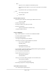
ELECTROSTATIC WARNING The PIC-WEB board is shipped in protective anti-static packaging. The board must not be subject to high electrostatic potentials. General practice for working with static sensitive devices should be applied when working with this board. BOARD USE REQUIREMENTS Cables: Depends on the used programming/debugging tool. It could be 1.
PROCESSOR FEATURES PIC-WEB board uses CPU PIC18F67J60 from Microchip with these features: Operating Frequency – DC – 41.
MAC: Support for Unicast, Multicast and Broadcast packets Programmable Pattern Match of up to 64 bytes within packet at user-defined offset Programmable wake-up on multiple packet formats PHY: Wave shaping output filter Loopback mode Flexible Oscillator Structure: Selectable System Clock derived from single 25 MHz external source: 2.78 to 41.
Low-Power, High-Speed CMOS Flash Technology: Self-reprogrammable under software control C compiler Optimized Architecture for re-entrant code Power Management Features: Run: CPU on, peripherals on Idle: CPU off, peripherals on Sleep: CPU off, peripherals off Priority Levels for Interrupts 8x8 Single-Cycle Hardware Multiplier Extended Watchdog Timer (WDT): Programmable period from 4 ms to 134s Single-Supply 3.
BLOCK DIAGRAM Page 7 of 36
MEMORY MAP of PIC18F67J60 Page 8 of 36
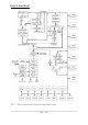
SCHEMATIC RST R8 V+ 6 3 C1- V- 4 C2+ 5 C2- RS232 DB9_female 6 7 8 9 1 C1+ 2 14 7 1 2 3 4 5 13 8 R1IN R2IN C22 100nF 20pF C4 C23 100nF 20pF C5 11 10 T1IN T2IN T1OUT T2OUT CTS R24 RTS 12 9 R1OUT R2OUT 16 VCC Q1 25MHz/5X3,2MM R9 GND_ 1M 39 40 GND 46 47 T PINT PIN+ TXD1 EXT-29 200R RXD1 EXT-30 T POUT - 50 T POUT + 51 BH34S R10 BH34S 2k/1% U3PWR 15GND 18 3.3V U3 MAX3232 C20 100nF C21 100nF 7 RST 53 270/1% C6 10 220nF 3.3V 3.
BOARD LAYOUT POWER SUPPLY CIRCUIT PIC-WEB can take power from two sources: - PWR_JACK where (9-12) VDC is applied by external power source. EXT-20 pin VIN with the same voltage range. The board power consumption is: about 130 mA with all peripherals and MCU running at full speed. RESET CIRCUIT PIC-WEB reset circuit is made with R8 (10k) pull-up, R7 (330R) serial resistor and RST button. Although on the schematic is made provision for external reset through EXT-16 pin.
JUMPER DESCRIPTION 3.3V_E When this jumper is closed, it enables 3.3V board power supply. Default state is closed. SCL_E When this jumper is closed, it connects UEXT pin 5 (SCL) to UEXT pin 9 (SCK), respectively PIC18F67J60 pin 2 (RE0/P2D) to PIC18F67J60 pin 34 (RC3/SCK1/SCL1). Default state is opened. SDA_E When this jumper is closed, it connects UEXT pin 6 (SDA) to UEXT pin 7 (SDI), respectively PIC18F67J60 pin 1 (RE1/P2C) to PIC18F67J60 pin 35 (RC4/SDI1/SDA1). Default state is opened.
EXTERNAL CONNECTORS DESCRIPTION ICSP Pin # Signal Name 1 RST 2 VCC 3 GND 4 PGD 5 PGC 6 Not Connected RS232 Pin # Signal Name 1 Not Connected 2 T1OUT 3 R1IN 4 Not Connected 5 GND 6 Not Connected 7 R2IN 8 T2OUT 9 Not Connected PWR_JACK Pin # Signal Name 1 Power Input 2 GND Page 12 of 36
EXT Pin # Signal Name Pin # Signal Name 1 RA2/AN2/VREF– 2 RA3/AN3/VREF+ 3 RA4/T0CKI 4 RA5/AN4 5 RE0/P2D 6 RE1/P2C 7 RE2/P2B 8 RC2/ECCP1/P1A 9 RD0/P1B 10 RD1/ECCP3/P3A 11 RD2/CCP4/P3D 12 RB1/INT1 13 RB2/INT2 14 RB3/INT3 15 RB5/KBI1 16 RST 17 +3,3V 18 +3.3V 19 GND 20 VIN 21 RE3/P3C 22 RE4/P3B 23 RE5/P1C 24 RF1/AN6/C2OUT 25 RF2/AN7/C1OUT 26 RF5/AN10/CVREF 27 RF6/AN11 28 RG4/CCP5/P1D 29 CTS 30 RTS 31 NC 32 NC 33 3.
UEXT Pin # Signal Name 1 VCC 2 GND 3 TXD1 4 RXD1 5 SCL 6 SDA 7 SDI 8 SDO 9 SCK 10 UEXT_#CS LAN Pin # Signal Name 1 TPOUT+ 2 TPOUT- 3 3.
MECHANICAL DIMENSIONS Page 15 of 36
Connecting and testing the board The PIC-WEB rev.C manufactured after 1 april 2014, comes with a default code that content an Internet Bootloader and a demo program (web-server) based on Microchip's TCP/IP stack version 5.42.08 included in "Microchip Libraries for Applications" released on 15 june 2013. The bootloader mode makes possible update of the firmware using LAN connection and TFTP.exe (see pages 28-29 of this manual or the README.txt inside the zip for more details) instead of programmer.
NOTE: The field “Serial line to connect to” should be with value depending on the com port where you have connected the board. You can check that on the device manager menu , category “Ports (COM & LPT)”. These are the basic steps to configure the connection. If you want to see what you are typing you should activate the echo.
After this setup the connection with the PIC-WEB should be ready, but the console will not show anything!. That’s because the board is not running on configuration mode. To run on that mode you just need to push the “BUT” button on the board. Keep it pressed while you push the “RST” button. A menu will immediately appear on your console terminal (in our example PuTTY) showing following options: The third option allow you to change the board IP number.
This configuration will let you test the board directly from your PC but isn’t too useful. The fun stuff begins when you have the PIC-WEB connected to internet. Just imagine your sensor monitor project, but now you will be able to see the information anywhere just browsing the address of the board! Test WEB page: As it was mentioned above, the PIC-WEB board has an embedded web server and a demo page. The page shows some of the features of the board and like peripherals and UEXT interfaces demo.
Page 20 of 36
To toggle the status LED of the board (PIC-WEB) you can click on the green dot under the caption “LEDs:”. By clicking on this dot you are changing the state of the pin, see how the led switch on or switch off. From the I2C Demo menu you can send command via UEXT to a MOD connected to the extension.
Uploading pages to the server There are 2 easy ways to upload pages to the server, but you will always need to convert the files you want to upload in a MPFS file format. One other way is to include the web page on the source code and link it in a project, but if we did it in this way we won’t use the external Flash (AT45DB011) included in the platform wasting program memory, that is reason this method will not be included in this manual.
A very handy feature of the utility is point 4, which may be used to automatically upload the image to the board after a successful convertion. Enter the IP of your board and leave the other fields at defaults. Press the 'Generate and Upload' and wait for your new image to be generated and uploaded. This is a sample of the result of a successful upload: Please note that an image file (in this case MPFSImg.
Now point to the image file and press 'Upload'. Sit back and relax while the upload takes place and then navigate to the home page to behold the new page just uploaded. The result will be: Installing the development environment The web page that we wrote in last chapter obviously doesn’t have any utility for any application at all. The idea of the PIC-WEB is to have control of the PIC18F67J60 features over the net using dynamics web pages or others TCP/IP protocols included in the Microchip Stack.
MPLAB C18 Compiler MPLAB C18 is a C compiler intended for the PIC18 family from Microchip. In our case is the needed compiler because the PIC-WEB platform uses the PIC18F67J60. This software converts C code into PIC18 machine code and link them together into a “*.HEX” file with the proper memory mapping for the microcontroller just ready to be programmed on it. Installation: After downloading you must execute the installation file (something like “MPLAB C18 v3.44.exe”) and follow the usual steps.
Programmer There are several ways to program a PIC, but the easiest and proper way to program the PIC-WEB is using a compatible programmer with an ISCP connector and compatible with MPLAB IDE. For this purpose it will be used an USB programmer compatible with MPLAB 8.92 and MPLABX 1.95 PIC-Kit3 sold by Olimex. PIC-KIT3: to use this programmer first of all you must have it connected to the PC trough an USB cable. Then you must select in MPLAB IDE – Configure → Select Device... A new window will appear.
Then you must select in MPLAB IDE – Programmer → Select Programmer → PICKit 3. Wait while MPLAB is downloading operation system, and after Pic-Kit3 is connected – check in menu Programmer – Settings – Power – there is option – Power target circuit from PicKit3 – this option should be forbidden, you could not select it. Now it is safe to connect the programmer to your target board trough an ISCP cable. The PIC-WEB should be connected to the power supply.
Programming via LAN BootLoader (BL) All mentioned in the previous chapter is about the old fashion programming using ICSP programmer. The latest demo (which is uploaded on the new PIC-WEB boards) provides a BL that makes possible remotely updating the firmware without programmer! To do this you must have: 1) already uploaded BL – as it was mentioned above the new boards will have it, but the older won't.
3) Uploading the hex via Internet BL – go to Start Menu → Run → cmd.exe. Prepare to trigger the uploading by entering the command line. The format is: tftp put Now reset the board, within next 4 seconds (while BL is active) trigger the command in console and wait few seconds until uploading is complete.
PIC-WEB Software After downloading the necessary PIC-WEB software and executing the instructions in “README.txt” file, you will have a working demo. Open this project “\PIC-WEB 5.42 UEXT Full\TCPIP\Demo App\PIC-WEB 5.42 Demo.mcp” Now is time to compile! If there aren’t bad configuration the compilation must be successful, that means that you have to get the “BUILD SUCCEEDED” message on the output window.
Dynamic Web Pages Creation For dynamic web pages creation you should refer to .\Microchip\Help\TCPIP Stack Help.chm at your computer. But since all help files are removed from the demo zip with the idea to be as small as possible if you want to read the help files you will have to download the Microchip Libraries for Applications v2013-06-15 from here: http://www.microchip.com/pagehandler/en-us/devtools/mla/.
Restore procedure: If you want to restore Olimex's original software you should program PIC18F67J60 with “\PIC-WEB 5.42 UEXT Full\TCPIP\Prebuilt\Bootloader+Demo.hex” from MPLAB IDE. After you have load this “*.hex” file, you should open “\PIC-WEB 5.42 UEXT Full\Microchip\TCPIP Stack\Utilities\TCPIP Discoverer.jar” Click on the button “Discover Devices” and the IP address of PIC-WEB will be discovered (for example - 192.168.0.171).
AVAILABLE DEMO SOFTWARE Microchip TCP/IP Stack 5.42 – modified for PIC-WEB REV.C, suitable both for MPLAB 8.xx and MPLAB X Microchip TCP/IP Stack 5.31 – modified for PIC-WEB REV.C, suitable only for MPLAB 8.xx, created by Paolo Chiarabaglio Production test based on TCP/IP Stack 5.00 – modified for PIC-WEB REV.C, suitable only for MPLAB 8.
ORDER CODE PIC-WEB - completely assembled and tested. How to order? You can order directly from our e-shop or from any of our distributors. The list of distributors is available at the following address: https://www.olimex.com/Distributors/ Check our web https://www.olimex.com/ for more info. Revision history: Board's revision: Rev. C - created May 2011 Manual's revision: Rev. Initial - created November 2012 Manual's revision: Rev. B - created December 2012 Manual's revision: Rev.
Disclaimer: © 2012 Olimex Ltd. Olimex®, logo and combinations thereof, are registered trademarks of Olimex Ltd. Other product names may be trademarks of others and the rights belong to their respective owners. The information in this document is provided in connection with Olimex products. No license, express or implied or otherwise, to any intellectual property right is granted by this document or in connection with the sale of Olimex products. The Hardware project is closed-source project.
For product support, hardware information and error reports mail to: support@olimex.com. Note that we are primarily a hardware company and our software support is limited. Please consider reading the paragraph below about the warranty of Olimex products. Warranty and returns: Our boards have lifetime warranty against manufacturing defects and components. During development work it is not unlikely that you can burn your programmer or development board.