STM32-E407 development board USER’S MANUAL Revision E, December 2013 Designed by OLIMEX Ltd, 2012 All boards produced by Olimex LTD are ROHS compliant
OLIMEX© 2013 STM32-E407 user's manual DISCLAIMER © 2013 Olimex Ltd. Olimex®, logo and combinations thereof, are registered trademarks of Olimex Ltd. Other product names may be trademarks of others and the rights belong to their respective owners. The information in this document is provided in connection with Olimex products. No license, express or implied or otherwise, to any intellectual property right is granted by this document or in connection with the sale of Olimex products.
OLIMEX© 2013 STM32-E407 user's manual Table of Contents DISCLAIMER............................................................................................................. 2 CHAPTER 1 OVERVIEW......................................................................................... 5 1. Introduction to the chapter.......................................................................................................5 1.1 Features...........................................................................
OLIMEX© 2013 STM32-E407 user's manual 6.11 BOOT connector.................................................................................................................. 20 6.12 Jumper description..............................................................................................................20 6.12.1 PWR_SEL...................................................................................................................................................20 6.12.2 B1_1/B1_0 and B0_1/B0_0.....
OLIMEX© 2013 STM32-E407 user's manual CHAPTER 1 OVERVIEW 1. Introduction to the chapter Thank you for choosing the STM32-E407 single board computer from Olimex! This document provides a user’s guide for the Olimex STM32-E407 board. As an overview, this chapter gives the scope of this document and lists the board’s features. The differences between the members of the STM32-E407 and STM32-H407 boards are mentioned. The document’s organization is then detailed.
OLIMEX© 2013 STM32-E407 user's manual TON of GPIO pins available on a number of headers. The board's Arduino platform headers give another option for enthusiasts who wish to implement support for Arduino/Maple/Pinguino shields giving the board additional features altogether with the option to add Olimex extension modules on the OLIMEX UEXT. All of the above options make the board quite versatile and suitable for numerous tasks and situations.
OLIMEX© 2013 STM32-E407 user's manual CHAPTER 2 SETTING UP THE STM32-E407 BOARD 2. Introduction to the chapter This section helps you set up the STM32-E407 development board for the first time. Please consider first the electrostatic warning to avoid damaging the board, then discover the hardware and software required to operate the board. The procedure to power up the board is given, and a description of the default board behavior is detailed. 2.
OLIMEX© 2013 STM32-E407 user's manual 2.3 Powering the board The board is powered in one of the following ways: 1) by PWR jack, 2)by JTAG/SWD programmer (3)by USB-OTG. The PWR jack should be supplied from a 6V to 16V source with maximum current of 1A from the power jack. Without additional components and peripherals (no microSD card mounted, nothing connected to the USB, etc.) the typical consumption is 30mA @ 12V. For the European customers we sell an affordable power supply adapter 12V/0.5A - SY0612E.
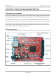
OLIMEX© 2013 STM32-E407 user's manual CHAPTER 3 STM32-E407 BOARD DESCRIPTION 3. Introduction to the chapter Here you get acquainted with the main parts of the board. Note the names used on the board differ from the names used to describe them. For the actual names check the STM32-E407 board itself. The board comes with a bag with 4 headers for the Arduino/Maple/Pinguino platform which were left unsoldered in case you don't wish to use those environments or you don't plan on using shields.
OLIMEX© 2013 STM32-E407 user's manual 3.2 Layout (bottom view) On the bottom there are three tables printed – general jumper table, boot mode jumper table, power mode jumper table. The default positions of the tables are also shown.
OLIMEX© 2013 STM32-E407 user's manual CHAPTER 4 THE STM32F407ZGT6 MICROCONTROLLER 4. Introduction to the chapter In this chapter is located the information about the heart of STM32-E407 – its Cortex-M4F microcontroller. The information is a modified version of the datasheet provided by its manufacturers from ST. 4.
OLIMEX© 2013 STM32-E407 user's manual SDIO interface Advanced connectivity USB 2.0 full-speed device/host/OTG controller with on-chip PHY USB 2.
OLIMEX© 2013 STM32-E407 user's manual CHAPTER 5 CONTROL CIRCUITY AND HARDWARE MODULES 5. Introduction to the chapter Here you can find information about reset circuit and quartz crystals locations, the power supply circuit is discussed. 5.1 Reset STM32-E407's reset circuit includes R5 (10KΩ), R6 (1 KΩ), C19 (100nF) and a RESET button. 5.2 Clocks There are two quartz crystals available on the board: 12 MHz quartz crystal Q1 is connected to pins 23 and 24 of the CORTEX-M4F processor.
OLIMEX© 2013 STM32-E407 user's manual CHAPTER 6 CONNECTORS AND PINOUT 6. Introduction to the chapter In this chapter are presented the connectors that can be found on the board all together with their pinout and notes about them. Jumpers functions are described. Notes and info on specific peripherals are presented. Notes regarding the interfaces are given. Note that slashed signals (xxxx/yyyy) in the tables below might mean either multiplexing between signals or port name correspondence on the processor.
OLIMEX© 2013 STM32-E407 user's manual microSD card connector Pin # Signal name 1 DAT2/RES 2 CD/DAT3/CS 3 CMD/DI 4 VDD 5 SCL/SCLK 6 VSS 7 DAT0/RES 8 DAT1/RES Notice that the pad numeration is written at the bottom of STM32-E407 under the microSD card connector. When removing the card, please make sure that you release it from the connector by pushing and NOT by pulling the card directly (this can damage both the connector and the microSD card). 6.
OLIMEX© 2013 STM32-E407 user's manual Note DFU bootloader uses the USB_OTG1 port, and a "USB micro-A" cable is required. Pin # Signal Name 1 +5V_OTG1_PWR 2 USB_OTG1_D- 3 USB_OTG1_D+ 4 PA10/OTG1_FS_ID 5 GND 6.
OLIMEX© 2013 STM32-E407 user's manual 6.6 LAN connector Pin # Signal name 1 TX+ 2 TX- 3 VDD 4 NOT CONNECTED 5 NOT CONNECTED 6 NOT CONNECTED 7 RX+ 8 RX- LED Color Usage Right Green Link status Left Yellow Activity status 6.7 Arduino/Maple platform The Arduino/Maple platform connectors (2x6pin and 2x8pin plastic headers) are not mounted but are included in the package.
OLIMEX© 2013 STM32-E407 user's manual Arduino platform pinholes CON3 CON4 Pin Signal Name Processor pin# Pin Signal Name Processor pin# D0 PB7/USART1_RX 137 D8 PG12 35 D1 PB6/USART1_TX 136 D9 PG15 70 D2 PE2 1 D10 PA4 40 D3 PE4 3 D11 PB5 43 D4 PE5 4 D12 PA6 42 D5 PR6 5 D13 PA5 41 D6 PG7 92 GND AGND 31 D7 PG8 93 AREF AREF 32 6.
OLIMEX© 2013 STM32-E407 user's manual PF PG Pin # Signal name Pin # Signal name Pin # Signal name Pin # Signal name 1 +3.3V 11 PF8/A3* 1 +3.
OLIMEX© 2013 STM32-E407 user's manual Pin # Signal name 1 VBAT 2 GND The pin names are also written on the bottom of the board in the base of the connector. 6.11 BOOT connector The best use for the GND, RX3, TX3 pins from the BOOT connector would be getting the output of the available demo program on a computer terminal via USB-SERIAL-CABLE-F (https://www.olimex.com/dev/usb-serial-cable.
OLIMEX© 2013 STM32-E407 user's manual If B0_1 is closed there are two variants depending on the state of B1_1/B1_0 jumper – if B0_1 is closed and B1_0 is closed the board will try to boot from System Memory. If B0_1 is closed and B1_1 is closed bootloader must be located in the Embedded SRAM. The default positions are B0_0 and B1_0 (Boot from User Flash Memory). 6.12.3 R-T This is SMD type jumper. If you close/solder this jumper RST and TRST at the JTAG will be connected.
OLIMEX© 2013 STM32-E407 user's manual WKUP button – can be used as user button User LED + Power LED Page 22 of 30
OLIMEX© 2013 STM32-E407 user's manual CHAPTER 7 BLOCK DIAGRAM AND MEMORY 7. Introduction to the chapter On the next page you can find a memory map for this family of processors. It is strongly recommended to refer to the original datasheet released by STMicroelectronics for one of higher quality. 7.
OLIMEX© 2013 STM32-E407 user's manual 7.
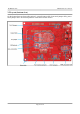
OLIMEX© 2013 STM32-E407 user's manual CHAPTER 8 SCHEMATICS 8. Introduction to the chapter In this chapter are located the schematics describing logically and physically STM32-E407. 8.1 Eagle schematic STM32-E407 schematic is visible for reference here. You can also find them on the web page for STM32-E407 at our site: https://www.olimex.com/Products/ARM/ST/STM32-E407/. They are located in HARDWARE section. The EAGLE schematic is situated on the next page for quicker reference.
OLIMEX© 2013 STM32-E407 user's manual Page 26 of 30
OLIMEX© 2013 STM32-E407 user's manual 8.2 Physical dimensions Note that all dimensions are in millimeters. The three highest elements on the board in order from the tallest to the shortest are: capacitor C50 – 17.2mm (0.677'') over the pcb; LAN connector – 13.6mm (0.535''); capacitors C42 and C48 – 11.5mm (0.453''). Note that the above measures does not include the PCB.
OLIMEX© 2013 STM32-E407 user's manual CHAPTER 9 REVISION HISTORY AND SUPPORT 9. Introduction to the chapter In this chapter you will find the current and the previous version of the document you are reading. Also the web-page for your device is listed. Be sure to check it after a purchase for the latest available updates and examples. 9.1 Document revision Revision Changes Modified page# A, 25.07.12 Initial Creation All B, 02.08.
OLIMEX© 2013 E STM32-E407 user's manual 1. R5 was changed from 10k/1% to 10k; 2. R70(0R) was changed to 10k and renamed to R13, added was C26=10uF/6.3V and RST connection was removed from the PHY!; 3. SD/MMC package was changed to the newer version (much more universal); 4. WKUP and RESET packages were changed to WSTAKT_6X3.5_SMD_NOCREAM; 5. Everything is renumbered, so there are no missing numbers. 6. C4 was changed from 100nF to 10uF/6.3V; 7. Added is R54 = 47k pull-up to Rx line; 9.
OLIMEX© 2013 STM32-E407 user's manual 9.4 Product support For product support, hardware information and error reports mail to: support@olimex.com. All document or hardware feedback is welcome. Note that we are primarily a hardware company and our software support is limited. Please consider reading the paragraph below about the warranty of Olimex products. All goods are checked before they are sent out.